Applications information – Rainbow Electronics MAX1686H User Manual
Page 6
MAX1686/MAX1686H
3V to 5V Regulating
Charge Pumps for SIM Cards
6
_______________________________________________________________________________________
1µA. Other features include soft-start, undervoltage
lockout, and short-circuit protection.
Charge-Pump Control
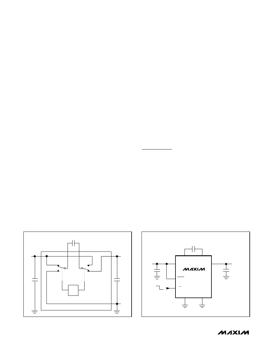
Figure 2 shows an idealized, unregulated charge-pump
voltage doubler. The oscillator runs at a 50% duty
cycle. During one half of the period, the transfer capac-
itor (C
X
) charges to the input voltage. During the other
half, the doubler stacks the voltage across C
X
and the
input voltage, and transfers the sum of the two voltages
to the output filter capacitor (C
OUT
). The MAX1686 uses
Skip Mode control to regulate its output voltage and to
achieve good efficiency over a large output current
range. When the comparator detects that the output
voltage is too low, the 1MHz oscillator is enabled and
C
X
is switched. When the output voltage is above regu-
lation, the oscillator is disabled and C
X
is connected at
the input.
Soft-Start
In the 5V mode (3/5 = GND), the start-up current is lim-
ited by the soft-start control to typically 200mA, inde-
pendent of the load. Until the output voltage reaches
V
IN
/ 2, the input is connected to the output through a
50
Ω
series P-channel MOSFET and the charge pump
is disabled. For V
IN
/ 2 < V
OUT
< 4.75V (5.00V for
MAX1686H) and for a maximum of 2ms the charge
pump is active, but R
ON
of the switch S2 is limited to
50
Ω
. This limits typical current surges associated with
charge pumps at start-up. When soft-start is complete,
V
OUT
> 4.75V (5.00V for MAX1686H) or 2ms (whichever
occurs first), switch S2’s on-resistance is decreased to
minimize losses.
In 3V mode (3/5 = IN), the start-up current is limited by
the 50
Ω
series P-channel MOSFET connected between
IN and OUT until the output voltage reaches V
IN
/ 2. For
V
OUT
> V
IN
/ 2, R
ON
is reduced to 2.5
Ω
.
With a 500
Ω
load the device turns on in less than 1.5ms
(see
Typical Operating Characteristics
for graphs of
start-up waveforms).
Shutdown Mode
Driving SHDN low places the device in shutdown mode,
which disables the oscillator, the control logic, and the
reference. Placing the device in shutdown mode
reduces the no-load supply current to less than 1µA; the
output is actively discharged through the internal N-
channel FET and disconnected from the input. In normal
operation, SHDN is driven high or connected to IN.
Applications Information
Capacitor Selection
The MAX1686 requires only three external capacitors.
The capacitor values are closely linked to the output
current capability, noise, and switching frequency. The
1MHz oscillator frequency minimizes capacitor size
compared to lower-frequency charge pumps.
Generally, the transfer capacitor (C
X
) will be the
smallest, the input capacitor (C
IN
) will be twice the size
of C
X
, and the output capacitor (C
OUT
) can be from 10
to 50 times C
X
. The suggested capacitor values are
C
IN
= 0.1µF, C
X
= 0.047µF, and C
OUT
= 2.2µF as
shown in Figure 3. For input voltages as low as 2.7V,
the following values are recommended: C
IN
= 0.47µF,
C
X
= 0.22µF, and C
OUT
= 10µF. Table 1 lists the perfor-
C
X
OSC
CXP
CXN
GND
IN
S1
S2
OUT
C
IN
C
OUT
Figure 2. Unregulated Voltage Doubler
MAX1686
IN
3
8
2
1
4
5
6
7
CXN
CXP
GND
PGND
C
IN
0.1
µ
F
3V
5V
INPUT
2.85V TO 4.2V
OUTPUT
V
IN
OR 4.75V AT 20mA
C
X
0.047
µ
F
C
OUT
2.2
µ
F
(CERAMIC)
SHDN
3/5
OUT
Figure 3. Standard Application Circuit