Rainbow Electronics MAX1446 User Manual
Page 15
MAX1446
10-Bit, 60Msps, +3.0V, Low-Power
ADC with Internal Reference
______________________________________________________________________________________
15
Differential Nonlinearity
Differential nonlinearity (DNL) is the difference between
an actual step width and the ideal value of 1LSB. A
DNL error specification of less than 1LSB guarantees
no missing codes and a monotonic transfer function.
Dynamic Parameter Definitions
Aperture Jitter
Figure 10 depicts the aperture jitter (t
AJ
), which is the
sample-to-sample variation in the aperture delay.
Aperture Delay
Aperture delay (t
AD
) is the time defined between the
falling edge of the sampling clock and the instant when
an actual sample is taken (Figure 10).
Signal-to-Noise Ratio (SNR)
For a waveform perfectly reconstructed from digital
samples, the theoretical maximum SNR is the ratio of
the full-scale analog input (rms value) to the rms quanti-
zation error (residual error). The ideal, theoretical mini-
mum A/D noise is caused by quantization error only
and results directly from the ADC’s resolution (N bits):
SNR
(MAX)
= (6.02 x N + 1.76)dB
In reality, there are other noise sources besides quanti-
zation noise: thermal noise, reference noise, clock jitter,
etc. SNR is computed by taking the ratio of the rms sig-
nal to the rms noise, which includes all spectral compo-
nents minus the fundamental, the first five harmonics,
and the DC offset.
Signal-to-Noise Plus Distortion (SINAD)
SINAD is computed by taking the ratio of the rms signal
to all spectral components minus the fundamental and
the DC offset.
Effective Number of Bits (ENOB)
ENOB specifies the dynamic performance of an ADC at
a specific input frequency and sampling rate. An ideal
ADC’s error consists of quantization noise only. ENOB
is computed from:
ENOB = (SINAD - 1.76dB) / 6.02dB
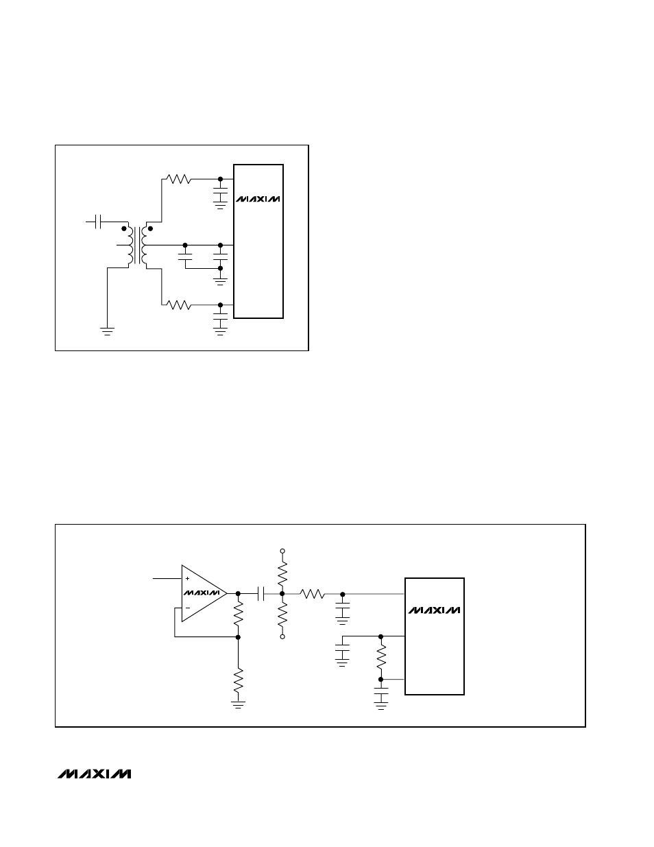
MAX1446
T1
N.C.
V
IN
6
1
5
2
4
3
22pF
22pF
0.1
µF
0.1
µF
2.2
µF
25
Ω
25
Ω
MINICIRCUITS
TT1–6
IN-
IN+
COM
Figure 8. Using a Transformer for AC-Coupling
MAX1446
0.1
µF
1k
1k
100
Ω
100
Ω
C
IN
COM
C
IN
IN+
IN-
0.1
µF
R
ISP
R
ISO
REFP
REFN
R
ISO
= 50
Ω
C
IN
= 22pF
V
IN
MAX4108
Figure 9. Single-Ended AC-Coupled Input