Rainbow Electronics MAX2673 User Manual
General description, Applications, Features
For free samples & the latest literature: http://www.maxim-ic.com, or phone 1-800-998-8800.
For small orders, phone 1-800-835-8769.
General Description
The MAX2660/MAX2661/MAX2663/MAX2671/MAX2673
miniature, low-cost, low-noise upconverter mixers are
designed for low-voltage operation and are ideal for
use in portable consumer equipment. Signals at the IF
input port are mixed with signals at the local oscillator
(LO) port using a double-balanced mixer. These
upconverter mixers operate with IF input frequencies
between 40MHz and 500MHz, and upconvert to output
frequencies as high as 2.5GHz.
These devices offer a wide range of supply currents and
output intercept levels to optimize system performance.
Supply current is essentially constant over the specified
supply voltage range. Additionally, when the devices are
in a typical configuration with V
SHDN
= 0, a shutdown
mode reduces the supply current to less than 1µA.
The MAX2660/MAX2661/MAX2663/MAX2671 are
offered in the space-saving 6-pin SOT23 package. For
applications requiring balanced IF ports, choose the
MAX2673 in the 8-pin µMAX package.
Applications
400MHz/900MHz/2.4GHz ISM
Hand-Held Radios
Wireless Local Area Networks (WLANs)
IEEE 802.11 and Wireless Data
Personal Communications Systems (PCS)
Cellular and Cordless Phones
Features
♦ RF Output Frequencies: 400MHz to 2.5GHz
♦ Low Noise Figure: 9.3dB (900MHz, MAX2671)
♦ +2.7V to +5.5V Single Supply
♦ High Output Intercept Point (OIP3)
5.9dBm at 4.8mA (MAX2660)
7.1dBm at 8.3mA (MAX2661)
0.7dBm at 3.0mA (MAX2663)
9.6dBm at 11.8mA (MAX2671)
7.6dBm at 20.5mA (MAX2673)
♦ 1µA Shutdown Mode
♦ Ultra-Small Surface-Mount Packaging
MAX2660/MAX2661/MAX2663/MAX2671/MAX2673
400MHz to 2.5GHz Upconverter Mixers
________________________________________________________________ Maxim Integrated Products
1
19-1382; Rev 1; 9/99
PART
MAX2660EUT-T
MAX2661EUT-T
MAX2663EUT-T
-40°C to +85°C
-40°C to +85°C
-40°C to +85°C
TEMP.
RANGE
PIN-
PACKAGE
6 SOT23-6
6 SOT23-6
6 SOT23-6
EVALUATION KIT MANUALS
FOLLOW DATA SHEET
Typical Operating Circuits and Functional Diagram appear at
end of data sheet.
Ordering Information
TOP
MARK
AAAF
AAAG
AAAL
MAX2671EUT-T
-40°C to +85°C
6 SOT23-6
AAAJ
MAX2673EUA
-40°C to +85°C
8 µMAX
—
PART
I
CC
(mA)
OUTPUT IP3 (dBm)
AT 900MHz
GAIN (dB)
AT 2450MHz
LO BUFFER
SINGLE-ENDED OR
DIFFERENTIAL IF
PACKAGE
MAX2660
4.8
5.9
4.6
No
Single Ended
6 SOT23
MAX2661
8.3
7.1
8.2
No
Single Ended
6 SOT23
MAX2663
3.0
0.7
1.4
No
Single Ended
6 SOT23
MAX2671
11.8
9.6
8.9
Yes
Single Ended
6 SOT23
MAX2673
20.5
7.6
8.6
Yes
Differential
8 µMAX
Selector Guide
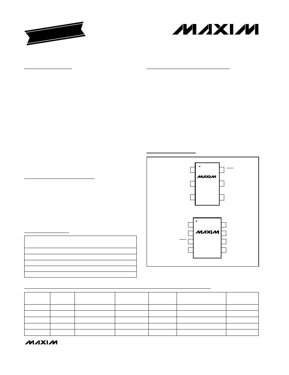
Pin Configurations
GND
RFOUT
IFIN
1
6
SHDN
5
V
CC
LO
MAX2660
MAX2661
MAX2663
MAX2671
SOT23-6
TOP VIEW
2
3
4
GND
RFOUT
V
CC
1
2
8
7
IFIN+
IFIN-
GND
SHDN
LO
µMAX
3
4
6
5
MAX2673