Definitions of specifications – Rainbow Electronics MAX101А User Manual
Page 10
MAX101A
500Msps, 8-Bit ADC with Track/Hold
10
______________________________________________________________________________________
______Definitions of Specifications
Signal-to Noise Ratio and Effective Bits
Signal-to-noise ratio (SNR) is the ratio between the RMS
amplitude of the fundamental input frequency to the
RMS amplitude of all other analog-to-digital (A/D) out-
put signals. The theoretical minimum A/D noise is
caused by quantization error and is a direct result of
the ADC’s resolution: SNR = (6.02N + 1.76)dB, where N
is the number of effective bits of resolution. Therefore, a
perfect 8-bit ADC can do no better than 50dB. The FFT
plots in the
Typical Operating Characteristics show the
output level in various spectral bands.
Effective bits is calculated from a digital record taken
from the ADC under test. The quantization error of the
ideal converter equals the total error of the device. In
addition to ideal quantization error, other sources of
error include all DC and AC nonlinearities, clock and
aperture jitter, missing output codes, and noise. Noise
on references and supplies also degrades effective bits
performance.
The ADC’s input is sine-wave filtered with an anti-alias-
ing filter to remove any harmonic content. The digital
record taken from this signal is compared against a
mathematically generated sine wave. DC offsets,
phase, and amplitudes of the mathematical model are
adjusted until a best-fit sine wave is found. After sub-
tracting this sine wave from the digital record, the resid-
ual error remains. The RMS value of the error is applied
in the following equation to yield the ADC’s effective
bits.
measured RMS error
Effective bits = N - log
2
—————————-
ideal RMS error
where N is the resolution of the converter. In this case,
N = 8.
The worst-case error for any device will be at the con-
verter’s maximum clock rate with the analog input near
the Nyquist rate (one-half the input clock rate).
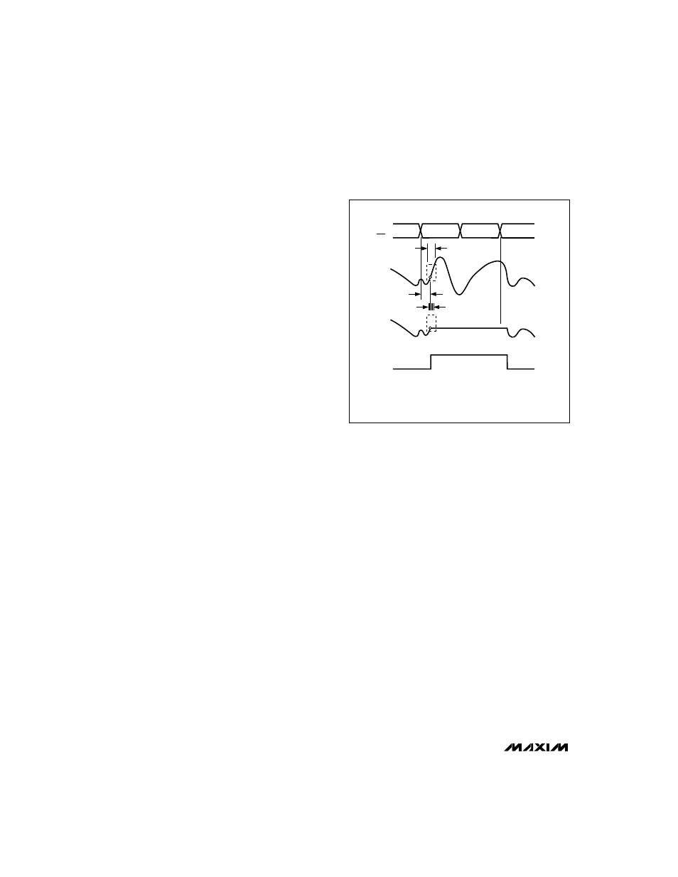
Aperture Width and Jitter
Aperture width is the time the T/H circuit takes to dis-
connect the hold capacitor from the input circuit (i.e., to
turn off the sampling bridge and put the T/H in hold
mode). Aperture jitter is the sample-to-sample variation
in aperture delay (Figure 4).
Error Rates
Errors resulting from metastable states may occur when
the analog input voltage, at the time the sample is
taken, falls close to the decision point for any one of the
input comparators. The resulting output code for many
typical converters can be incorrect, including false full- or
zero-scale output. The MAX101A’s unique design
reduces the magnitude of this type of error to 1LSB, and
reduces the probability of the error occurring to less than
one in every 10
15
clock cycles. If the MAX101A were
operated at 500MHz, 24 hours a day, this would translate
to less than one metastable state error every 46 days.
Integral Nonlinearity
Integral nonlinearity is the deviation of the transfer func-
tion from a reference line measured in fractions of 1LSB
using a “best straight line” determined by a least
square curve fit.
Differential Nonlinearity
Differential nonlinearity (DNL) is the difference between
the measured LSB step and an ideal LSB step size
between adjacent code transitions. DNL is expressed
in LSBs and is calculated using the following equation:
[V
MEAS
- (V
MEAS - 1
)] - LSB
DNL(LSB) = ——————————————-
LSB
where V
MEAS - 1
is the measured value of the previous
code.
A DNL specification of less than 1LSB guarantees no
missing codes and a monotonic transfer function.
SAMPLED
DATA (T/H)
T/H
CLK
CLK
ANALOG
INPUT
t
AD
TRACK
t
AJ
t
AW
TRACK
HOLD
APERTURE DELAY (t
AD
)
APERTURE WIDTH (t
AW
)
APERTURE JITTER (t
AJ
)
Figure 4. T/H Aperture Timing