Connection diagram, Ordering information, Pin description – Rainbow Electronics LM95010 User Manual
Page 2: Typical application
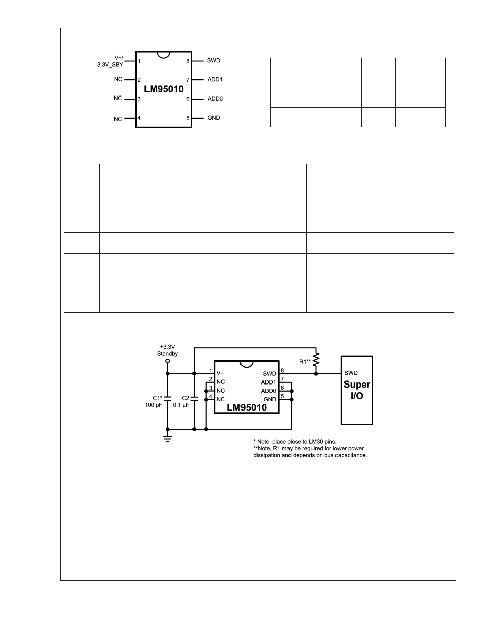
Connection Diagram
20082002
Ordering Information
Order
Number
Package
Marking
NS
Package
Number
Transport
Media
LM95010CIMM
T19C
MUA08A 1000 units in
tape and reel
LM95010CIMMX
T19C
MUA08A 3500 units in
tape and reel
Pin Description
Pin
Number
Pin Name
Type
Description
Typical Connection
1
V+/3.3V
SB
Power
Positive power supply pin +3.3V pin.
Should be powered by +3.3V Standby power.
This pin should be bypassed with a 0.1 µF
capacitor. A bulk capacitance of approximately
10 µF needs to be in the near vicinity of the
LM95010.
2-4
NC
Must be grounded.
5
GND
Power
Ground
System ground
6
ADD0
Input
Address select input that assigns the serial
bus device number
10k resistor to V+ or GND; must never be left
floating
7
ADD1
Input
Address select input that assigns the serial
bus device number
10k resistor to V+ or GND; must never be left
floating
8
SWD
Input/
Output
Single-wire Data, SensorPath serial
interface line; Open-drain output
Super I/O with 1.25k pull-up to 3.3V
Typical Application
20082003
FIGURE 1. LM95010 connection to SensorPath master such as a Super I/O.
LM95010
www.national.com
2