Rainbow Electronics LM95010 User Manual
Bus in msop8 package, General description, Features
LM95010
Digital Temperature Sensor with SensorPath
™
Bus in
MSOP8 Package
General Description
The LM95010 is a digital output temperature sensor that has
single-wire interface compatible with National Semiconduc-
tor’s SensorPath interface. It uses a
∆V
be
analog tempera-
ture sensing technique that generates a differential voltage
that is proportional to temperature. This voltage is digitized
using
a
Sigma-Delta
analog-to-digital
converter.
The
LM95010 is part of a hardware monitor system, comprised of
two parts: the PC System Health Controller (Master), such
as a Super I/O, and up to seven slaves of which four can be
LM95010s. Using SensorPath, the LM95010 will be con-
trolled by the master and report to the master its own die
temperature. SensorPath data is pulse width encoded,
thereby allowing the LM95010 to be easily connected to
many general purpose micro-controllers.
Features
n
SensorPath Bus
— 4 hardware programmable addresses
n
Temperature Sensing
— 0.25 ˚C resolution
— 127.75 ˚C maximum temperature reading
n
8-lead MSOP package
Key Specifications
n
Temperature Sensor Accuracy
±
2 ˚C (max)
n
Temperature Range
−20 ˚C to +125 ˚C
n
Power Supply Voltage
+3.0V to +3.6V
n
Power Supply Current
0.5 mA (typ)
n
Conversion Time
14 ms to 1456 ms
Applications
n
Microprocessor based equipment
— (Motherboards, Base-stations, Routers, ATMs, Point
of Sale, …)
n
Power Supplies
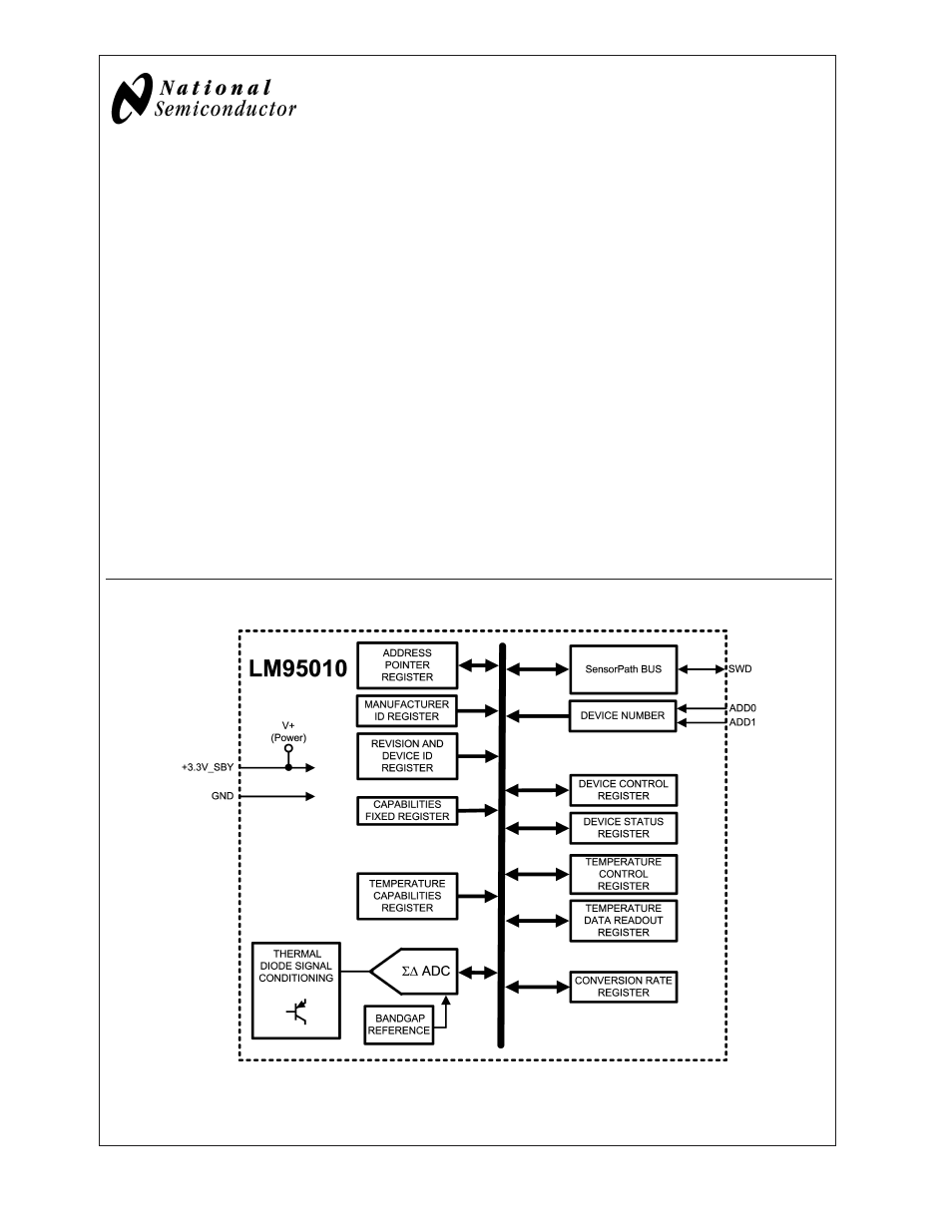
Block Diagram
20082001
SensorPath
™
is a trademark of National Semiconductor Corporation.
November 2003
LM95010
Digital
T
emperature
Sensor
with
SensorPath
Bus
in
MSOP8
Package
© 2003 National Semiconductor Corporation
DS200820
www.national.com
Document Outline
- LM95010
- General Description
- Features
- Key Specifications
- Applications
- Block Diagram
- Connection Diagram
- Ordering Information
- Pin Description
- Typical Application
- Absolute Maximum Ratings
- Operating Ratings (Notes , )
- DC Electrical Characteristics
- AC Electrical Characteristics
- FIGURE 2. Timing for Data Bits 0, 1 and Start Bit. See Section 1.2 "Bit Signaling" for further detai
- FIGURE 3. Timing for Attention Request and Reset. See Section 1.2 "Bit Signaling" for further detail
- FIGURE 4. ESD Protection Input Structure. Devices that are connected to a particular pin are marked
- Typical Performance Characteristics
- 1.0 Functional Description
- 2.0 Register Set
- 2.1 REGISTER SET SUMMARY
- 2.2 Device Reset Operation
- 2.3 DEVICE NUMBER (Addr 00o)
- 2.4 MANUFACTURER ID (Addr 01o)
- 2.5 DEVICE ID (Addr 02o)
- 2.6 CAPABILITIES FIXED (Addr 03o)
- 2.7 DEVICE STATUS (Addr 04o)
- 2.8 DEVICE CONTROL (Addr 05o)
- 2.9 TEMPERATURE MEASUREMENT FUNCTION (TYPE - 0001)
- 2.10 CONVERSION RATE (Addr 40o)
- 3.0 Applications Information
- Physical Dimensions