Ac electrical characteristics—max2653 – Rainbow Electronics MAX2653 User Manual
Page 7
MAX2651/MAX2652/MAX2653
GSM900 and DCS1800/PCS1900
Dual-Band, Low-Noise Amplifiers
_______________________________________________________________________________________
7
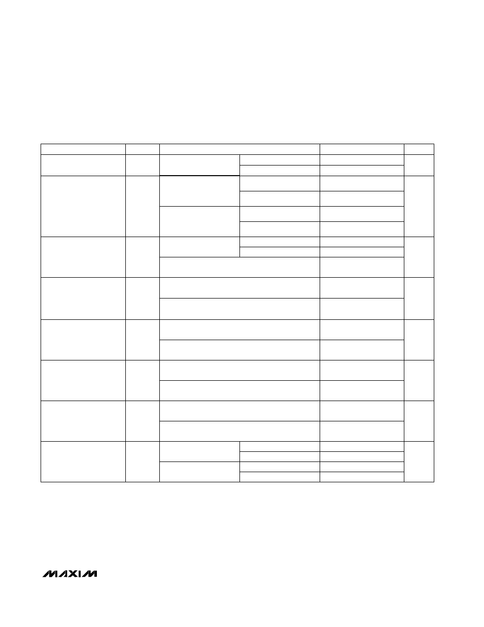
AC ELECTRICAL CHARACTERISTICS—MAX2653
(MAX2653 EV kit, f
IN
= 1850MHz (DCS band), f
IN
= 1960MHz (PCS band), P
IN
= -30dBm, input and output matching networks are
optimized for the frequency band of interest, all input/output ports terminated in 50
Ω, V
CC
= +3V, T
A
= +25°C, unless otherwise
noted.) (Note 2)
Note 2: Minimum and maximum limits are guaranteed by design and characterization, but not production tested.
Note 3: The part has been fully characterized at the specified frequency range. Operation outside of this range is possible but not
guaranteed.
Note 4: Specification excludes circuit board losses.
Note 5: Measured with two tones, f
IN1
= 1850MHz, f
IN2
= 1850.8MHz, P
IN
= -33dBm for each tone.
Note 6: Measured with two tones, f
IN1
= 945MHz, f
IN2
= 945.8MHz, P
IN
= -33dBm for each tone.
Note 7: Measured with two tones, f
IN1
= 1960MHz, f
IN2
= 1960.8MHz, P
IN
= -33dBm for each tone.
PCS band
DCS band
PCS band
DCS band
1.8
2.05
-4
0
16
20
1930
1990
-21
-18
-33
-29
PCS band
DCS band
PCS band
DCS band
DCS and PCS band, low-gain mode
(BAND = V
CC
, GAIN = GND)
High-gain mode (BAND
= GAIN = V
CC
)
Reverse Isolation
S
12
2
-35
-31
dB
-21
-18
Low-gain mode (BAND =
V
CC
, GAIN = GND)
DCS and PCS band, high-gain mode
(BAND = GAIN = V
CC
)
Output Return Loss
S
22
2
-12
-9.5
dB
-15
-12
DCS and PCS band, low-gain mode
(BAND = V
CC
, GAIN = GND)
DCS and PCS band, high-gain mode
(BAND = GAIN = V
CC
)
Input Return Loss
S
11
2
-11
-8.5
dB
-11
-9.5
DCS and PCS band, low-gain mode
(BAND = V
CC
, GAIN = GND)
-1
+1.5
DCS and PCS band, high-gain mode
(BAND = GAIN = V
CC
)
PARAMETER
SYMBOL
MIN
TYP
MAX
UNITS
Noise Figure (Note 4)
NF
1.7
1.9
-4
-2.5
-1
17
18.5
20
5.3
6.7
dB
Input Third-Order
Intercept Point
(Notes 5, 7)
IIP3
-10.5
-8.5
dBm
Input Frequency Range
(Note 3)
f
IN
1805
1880
MHz
Power Gain (Note 4)
G
dB
Input 1dB Compression
Point
IP
-1dB
-20
-18
dB
-9
-7
CONDITIONS
High-gain mode
(BAND = GAIN = V
CC
)
DCS and PCS band,
low-gain mode (BAND =
V
CC
, GAIN = GND)
DCS and PCS band,
high-gain mode
(BAND = GAIN = V
CC
)
DCS and PCS band, low-gain mode
(BAND = V
CC
, GAIN = GND)
DCS and PCS band, low-gain mode
(BAND = V
CC
, GAIN = GND)
DCS and PCS band, high-gain mode
(BAND = V
CC
, GAIN = GND)
BAND = V
CC
T
A
= +25°C
T
A
= +25°C
T
A
= -40°C to +85°C
T
A
= -40°C to +85°C