Max1673, Detailed description, Pin description – Rainbow Electronics MAX1673 User Manual
Page 6
MAX1673
Detailed Description
The MAX1673 new-generation, high-output-current,
regulated charge-pump DC-DC inverter provides up to
125mA. Designed specifically for compact applica-
tions, a complete regulating circuit requires only three
small capacitors and two resistors. The MAX1673
employs On-Demand™ regulation circuitry, providing
output regulation modes optimized for either lowest out-
put noise or lowest supply current. In addition, the
MAX1673 includes shutdown control.
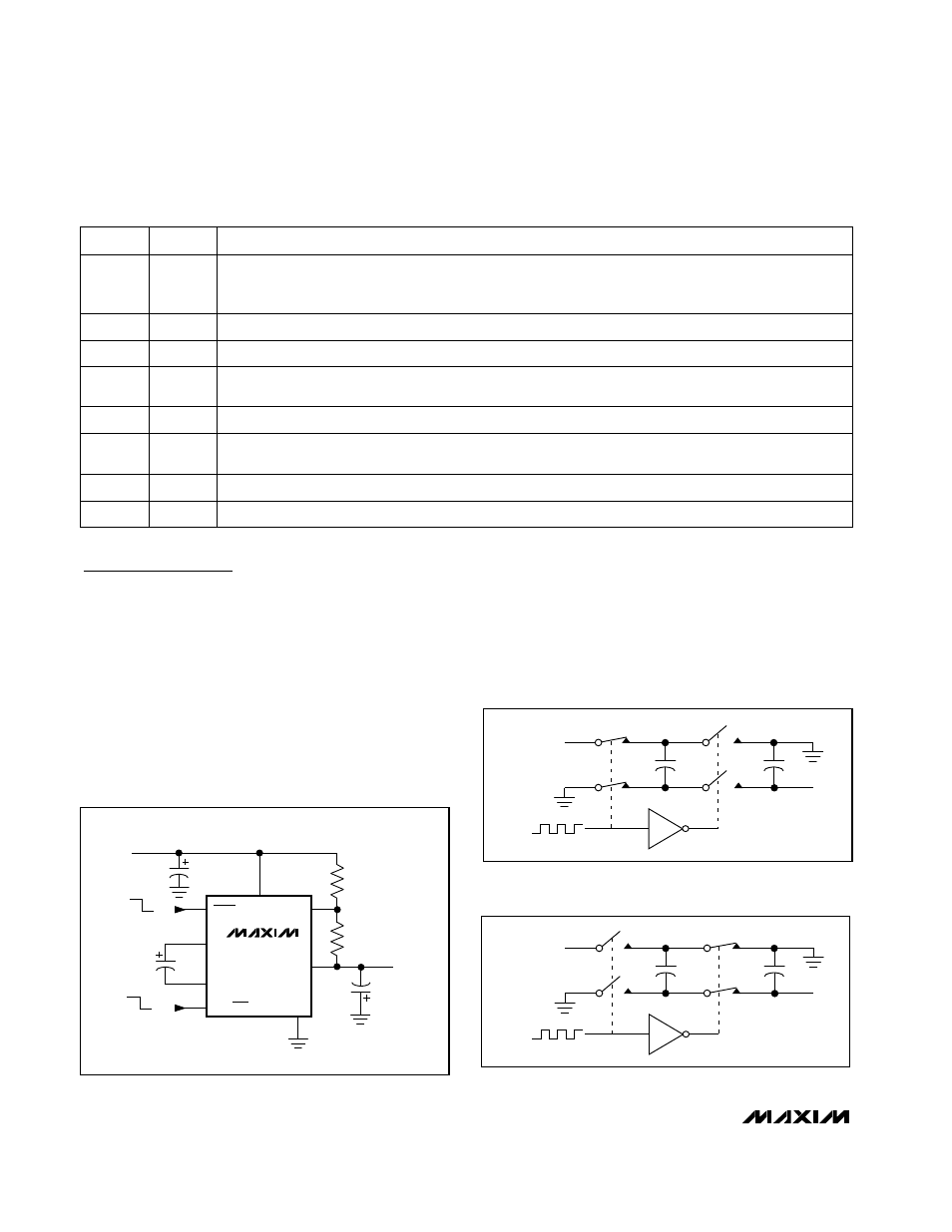
In Linear (LIN) mode or when heavily loaded in Skip
mode, the charge pump runs continuously at 350kHz.
During one-half of the oscillator period, switches S1 and
S2 close (Figure 2), charging the transfer capacitor
(C
FLY
) to the input voltage (CAP- = GND, and CAP+ =
IN). During the other half cycle, switches S3 and S4
close (Figure 3), transferring the charge on C
FLY
to the
output capacitor (CAP+ = GND, CAP- = OUT).
Regulated, 125mA-Output,
Charge-Pump DC-DC Inverter
6
_______________________________________________________________________________________
______________________________________________________________Pin Description
MAX1673
IN
INPUT
5.0V
OUTPUT
-3V
C
IN
10
µ
F
C
OUT
22
µ
F
C
FLY
2.2
µ
F
LIN/SKIP
FB
R1
100k
R1
60.4k
OUT
GND
CAP+
ON
OFF
4
2
3
SHDN
CAP-
LIN
SKIP
1
7
5
6
8
Figure 1. Standard Application Circuit
S2
OUT
C
OUT
C
FLY
S1
CAP+
CAP-
IN
S4
S3
350kHz
Figure 2. Charging C
FLY
S2
OUT
C
OUT
C
FLY
S1
IN
S4
S3
350kHz
CAP+
CAP-
Figure 3. Transferring Charge on C
FLY
to C
OUT
Inverting Charge-Pump Output
OUT
5
Feedback Input. Connect FB to a resistor-divider from IN (or other reference source) to OUT for regulated
output voltages (Figures 1 and 4).
FB
6
Ground
GND
7
Power-Supply Positive Voltage Input
IN
8
Shutdown Control Input. Drive SHDN low to shut down the MAX1673. Connect SHDN to IN for normal
operation. OUT connects to GND through a 1
Ω
(typical) resistor in shutdown mode.
SHDN
4
Negative Terminal of Flying Capacitor
CAP-
3
PIN
Positive Terminal of Flying Capacitor
CAP+
2
Regulation-Mode Select Input. Driving LIN/SKIP high or connecting it to IN selects LIN mode, with regula-
tion accomplished by modulating switch resistance. Driving LIN/SKIP low or connecting it to GND selects
Skip mode, where the device regulates by skipping charge-pump pulses.
LIN/SKIP
1
FUNCTION
NAME