Applications information – Rainbow Electronics MAX2644 User Manual
Page 5
MAX2644
2.4GHz SiGe, High IP3 Low-Noise Amplifier
_______________________________________________________________________________________
5
Applications Information
Input Matching
Input matching is required for optimum performance.
The MAX2644 requires a simple LC matching network,
as shown in the Typical Operating Circuit. To further
reduce cost and external component count, replace the
external inductor with a microstrip transmission line.
The Typical Operating Circuit shows the recommended
input matching network for the MAX2644 at 2450MHz.
These values are optimized for best simultaneous gain,
noise figure, and return loss performance.
V
CC
Line Bypassing
Bypassing the V
CC
line is necessary for optimum
gain/linearity performance. A transmission line and two
capacitors are required, as shown in the schematics in
Figures 1 and 2. The optimum dimensions and posi-
tions of the components are as follows: the output
transmission line dimension is 0.532in (length)
✕
0.012in
(width); the distance from C2 to the IC is 0.352in; and
the distance from C3 to the IC is 0.041in. Please refer
to Figures 1 and 2 for component values.
U1
MAX2644
SMA
RFIN
SMA
RFOUT
C1
33pF
L1
3.3nH
3
2
1
6
5
4
V
CC
GND
C3
15pF
Length = 400mils
C2
33pF
V
CC
GND
RFIN
GND
RFOUT
BIAS
GAIN: 16dB
IIP3: +1dBm
L2
3.9nH
R1
1.2k
Ω
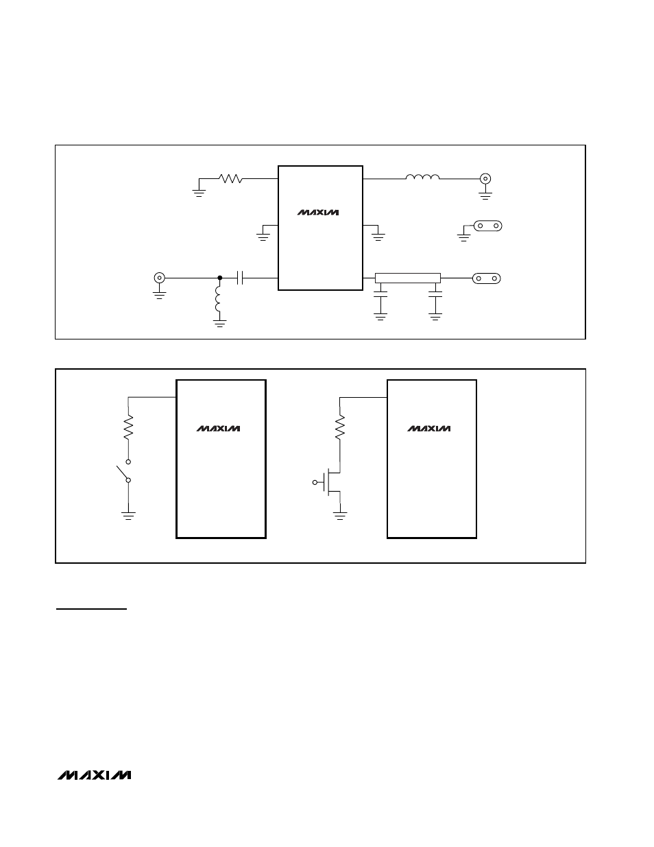
Figure 2. High Linearity Design
MAX2644
MAX2644
BIAS
BIAS
(a)
(b)
Figure 3. Recommended MAX2644 Standby Configurations