Electrical characteristics (continued) – Rainbow Electronics MAX744A User Manual
Page 3
MAX730A/MAX738A/MAX744A
5V, Step-Down,
Current-Mode PWM DC-DC Converters
_______________________________________________________________________________________
3
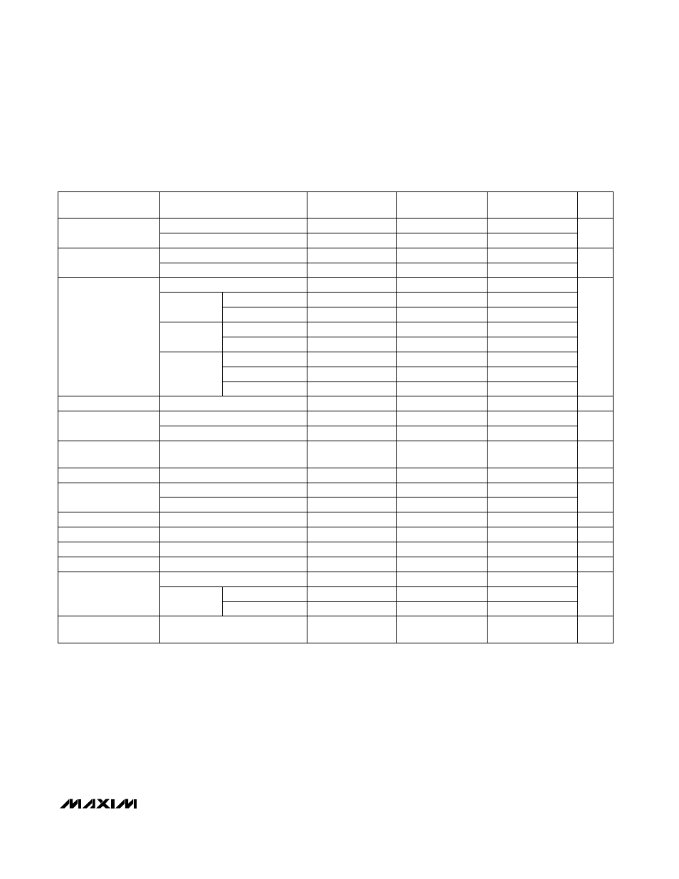
Note 1:
The standby current typically settles to 25µA (over temperature) within 2 seconds; however, to decrease test time, the part
is guaranteed at a 100µA maximum value.
ELECTRICAL CHARACTERISTICS (continued)
(Circuit of Figure 3, V+ = 9V for the MAX730A, V+ = 12V for the MAX738A/MAX744A, I
LOAD
= 0mA, T
A
= T
MIN
to T
MAX
,
unless otherwise noted.)
PARAMETER
I
LOAD
= 0mA to 300mA
MAX730A
MIN
TYP
MAX
Supply Current
(includes switch
current)
I
LOAD
= 0mA to 750mA
UNITS
V+ = 9.0V, I
LOAD
= 300mA
MAX738A
MIN
TYP
MAX
4.3
mA
MAX744AE
I
LX
= 500mA
6.0
100.0
6.0
100.0
6.0
100.0
µA
Standby Current
V
IH
0.0005
LX On Resistance
2.0
2.0
2.0
MAX744AC/AE
0.5
V
IL
MAX744A
MIN
TYP
MAX
0.25
0.25
0.25
V
0.5
0.0005
Shutdown Input
Threshold
%/mA
Shutdown Input
Leakage Current
V+ = 12V, I
LOAD
= 750mA
Load Regulation
0.0005
SHDN = 0V (Note 1)
0.5
1.7
3.0
1.7
3.0
1.7
3.0
159.0 185.0 212.5
Ω
MAX744AC/AE
1.2
2.5
V+ = 12V, LX = 0V
MAX744AM
1.0
3.0
1.0
1.0
V+ = 6.0V
to 9.0V
MAX744AC/AE
3.0
1.0
µA
Reference Drift
1.0
1.0
MAX744AM
µA
3.5
1.5
MAX744AM
V+ = 9.0V
to 12.0V
MAX744AC
4.0
50
50
LX Leakage Current
1.5
87
1.5
CONDITIONS
A
Short-Circuit Current
V+ rising
159.0
216.5
5.7
6.0
5.7
6.0
4.7
5.2
V+ falling
5.0
5.7
V
kHz
Undervoltage
Lockout
90
87
90
%
Efficiency
92
V+ = 6.0V
to 16.0V
V+ = 12V, T
A
= +25°C
Reference Voltage
1.15
1.23
1.30
1.15
1.23
1.30
1.15
1.23
1.30
V
50
130
160
190
130
170
210
ppm/°C
Oscillator Frequency
7500
7500
7500
Ω
Compensation Pin
Impedance
4.5
V+ = 12.0V
to 16.0V
MAX744AM