0 serial bus timing diagrams, Figure 7. timing diagrams, 0 application hints – Rainbow Electronics LM71 User Manual
Page 10: 0 serial bus timing diagrams 3.0 application hints
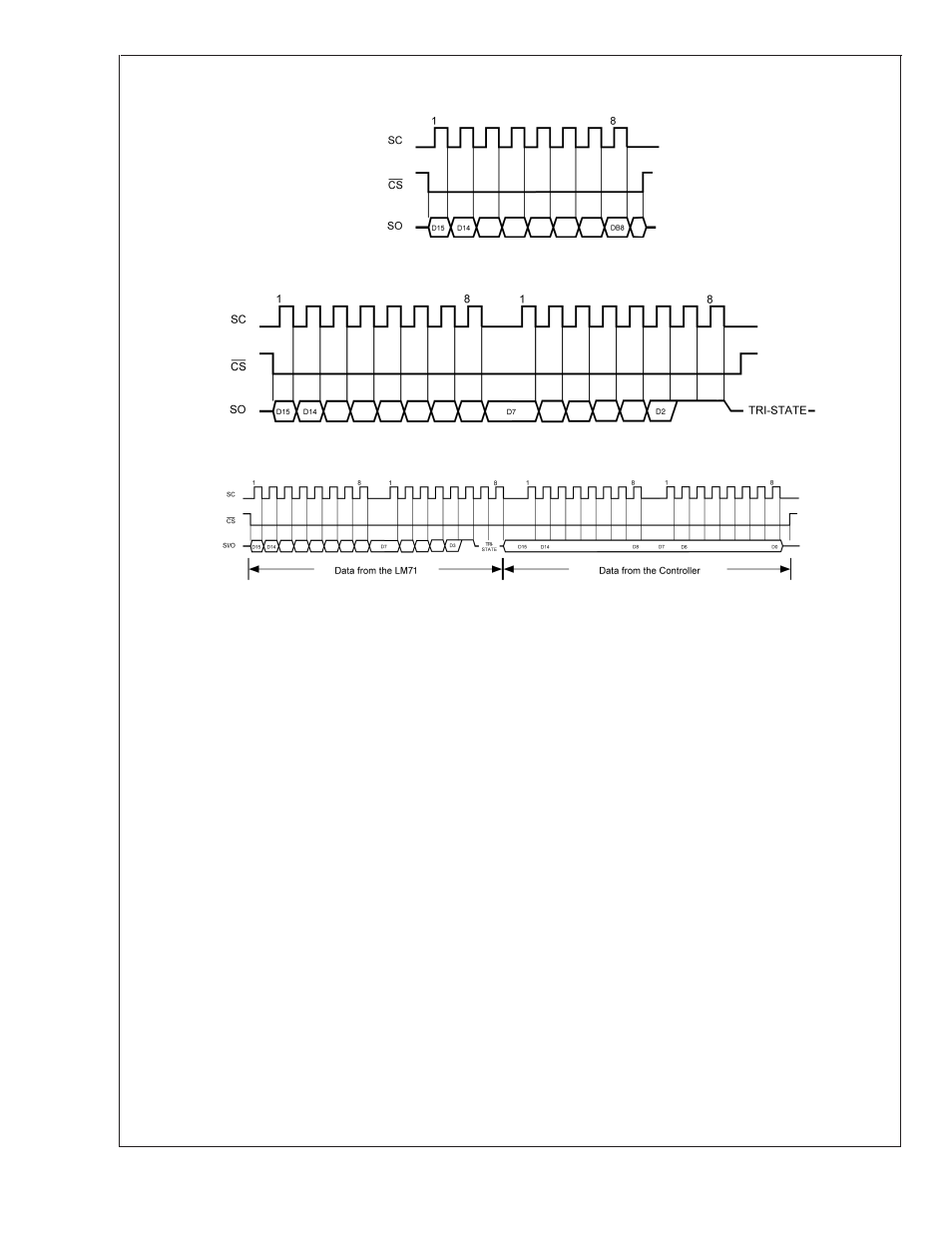
2.0 Serial Bus Timing Diagrams
3.0 Application Hints
To get the expected results when measuring temperature
with an integrated circuit temperature sensor like the LM71,
it is important to understand that the sensor measures its
own die temperature. For the LM71, the best thermal path
between the die and the outside world is through the LM71’s
pins. In the SOT23 package, all the pins on the LM71 will
have an equal effect on the die temperature. Because the
pins represent a good thermal path to the LM71 die, the
LM71 will provide an accurate measurement of the tempera-
ture of the printed circuit board on which it is mounted. There
is a less efficient thermal path between the plastic package
and the LM71 die. If the ambient air temperature is signifi-
cantly different from the printed circuit board temperature, it
will have a small effect on the measured temperature.
In probe-type applications, the LM71 can be mounted inside
a sealed-end metal tube, and can then be dipped into a bath
or screwed into a threaded hole in a tank. As with any IC, the
LM71 and accompanying wiring and circuits must be kept
insulated and dry, to avoid leakage and corrosion. This is
especially true if the circuit may operate at cold temperatures
where condensation can occur. Printed-circuit coatings and
varnishes such as Humiseal and epoxy paints or dips are
often used to insure that moisture cannot corrode the LM71
or its connections.
20031714
a) Reading Continuous Conversion - Single Eight-Bit Frame
20031715
b) Reading Continuous Conversion - Two Eight-Bit Frames
20031718
c) Writing Shutdown Control
FIGURE 7. Timing Diagrams
LM71
www.national.com
10