Typical i/q application – Rainbow Electronics MAX107 User Manual
Page 15
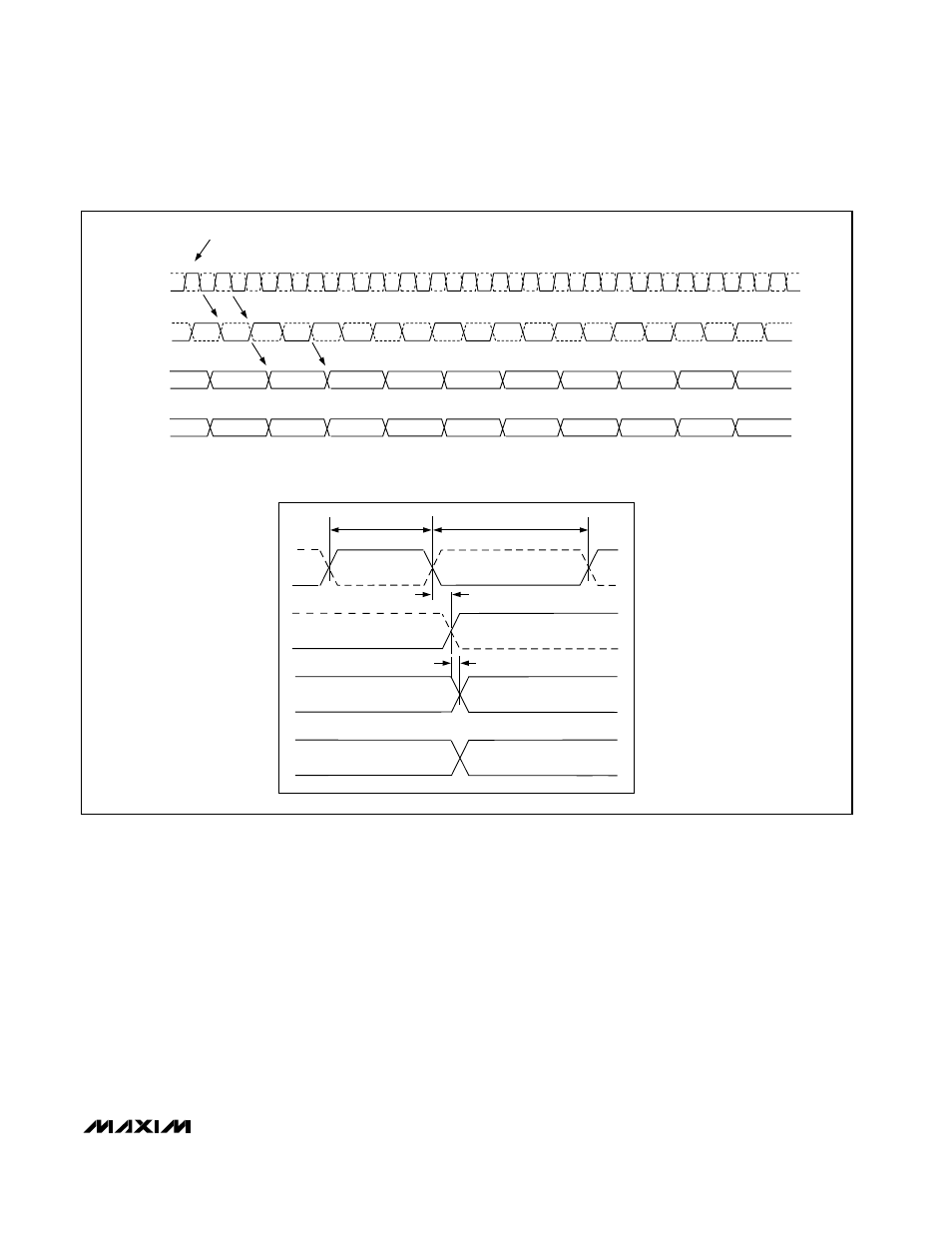
edge of the data ready clock. The auxiliary data port
always contains the older sample. The primary output
always contains the most recent data sample, regard-
less of the DREADY clock phase.
Figure 7 shows the
timing and data alignment of the auxiliary and primary
output ports in relationship with the CLK and DREADY
signals. Data in the primary port is delayed by five
clock cycles while data in the auxiliary port is delayed
by six clock cycles.
Typical I/Q Application
Quadrature amplitude modulation (QAM) is frequently
used in digital communication systems to increase
channel capacity. A QAM signal is modulated in both
amplitude and phase. With a demodulator, this QAM
signal gets downconverted and separated in its in-
phase (I) and quadrature (Q) components. Both I&Q
channels are digitized by an ADC at the baseband
level in order to recover the transmitted information.
Figure 8 shows a typical application circuit to directly
tune L-band signals to baseband, incorporating a
direct conversion tuner (MAX2108) and the MAX107 to
digitize I&Q channels with excellent phase- and gain-
matching. A front-end L-C filter is required for anti-alias-
ing purposes.
MAX107
Dual, 6-Bit, 400Msps ADC with On-Chip,
Wideband Input Amplifier
______________________________________________________________________________________
15
Figure 7. Output Timing Relationship Between CLK and DREADY Signals and Primary/Auxiliary Output Ports
CLK+
CLK-
DREADY +
DREADY -
AUXILIARY PORT DATA
PRIMARY PORT DATA
t
PWH
t
PWL
t
PD1
t
PD2
NOTE: THE LATENCY TO THE PRIMARY PORT IS FIVE CLOCK CYCLES, THE LATENCY TO THE AUXILIARY PORT IS SIX CLOCK
CYCLES. BOTH PRIMARY AND AUXILIARY DATA PORTS ARE UPDATED ON THE RISING EDGE OF THE DREADY+ CLOCK.
CLK-
CLK+
N
N+1
N+2
N+3
N+4
N+5
N
N+8
N+10
N+2
N+6
N+4
N+6
N+7
N+8
N+9
N+10
N+11
N+12
N+13
ADC SAMPLE
MAX107 ADCs SAMPLE ON THE RISING EDGE OF CLK+
CLK
DREADY
AUXILIARY
DATA PORT
PRIMARY
DATA PORT
DREADY-
DREADY+
N+14
N+15
N+16
N+17
N+18
N+19
N+9
N+11
N+3
N+1
N+7
N+5