Applications information – Rainbow Electronics MAX107 User Manual
Page 13
+1.2V, and must be differentially terminated at the far
end of each transmission line pair (true and comple-
mentary) with 100
Ω.
Out-Of-Range Operation
A single output pair (DOR+, DOR-) is provided to flag
an out-of-range condition, if either the I or Q channel is
out-of-range, where out-of-range is above +FS or below
-FS. It features the same latency as the ADCs output
data and is demultiplexed in a similar fashion. With a
400MHz system clock, DOR+ and DOR- are clocked at
up to 200MHz.
Applications Information
Single-Ended Analog Inputs
The MAX107 is designed to work at full-speed for both
single-ended and differential analog inputs without sig-
nificant degradation in its dynamic performance. Both
input channels I (INI+, INI-) and Q (INQ+, INQ-) have
2k
Ω impedance and allow for AC- and DC-coupled
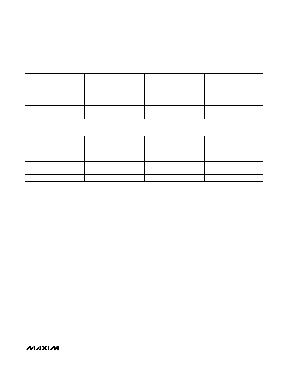
input signals. In a typical DC-coupled single-ended
configuration (Table 1), the analog input signals enter
the analog input amplifier stages at the in-phase-input
pins INI+/INQ+, while the inverted phase input INI-
/INQ- pins are AC-coupled to AGNDI/AGNDQ. Single-
ended operation allows for an input amplitude of
800mVp-p, centered around V
REF
.
Differential Analog Inputs
To obtain +FS digital outputs with differential input drive
(Table 2), 400mV must be applied between INI+ (INQ+)
and INI- (INQ-). Midscale digital output codes occur
when there is no voltage difference between INI+
(INQ+) and INI- (INQ-). For a -FS digital output code
both in-phase (INI+, INQ+) and inverted input (INI-,
INQ-) must see -400mV.
Single-Ended to Differential
Conversion Using a Balun
An RF balun (Figure 3) provides an excellent solution to
convert a single-ended signal to a fully differential sig-
nal, required by the MAX107 for optimum performance.
At higher frequencies, the MAX107 provides better
SFDR and THD with fully differential input signals over
single-ended input signals. In differential input mode,
even-order harmonics are suppressed and each input
requires only half the signal-swing compared to single-
ended mode.
Clock Input
The MAX107 features clock inputs designed for either
single-ended or differential operation with very flexible
input drive requirements. The clock inputs (AC- or DC-
coupled) provide a 5k
Ω input impedance to AV
CC
/2
and are internally buffered with a preamplifier to ensure
proper operation of the converter even with small-
amplitude sine-wave sources. The MAX107 was
MAX107
Dual, 6-Bit, 400Msps ADC with On-Chip,
Wideband Input Amplifier
______________________________________________________________________________________
13
IN-PHASE INPUTS
(INI+, INQ+)
INVERTED INPUTS
(INI-, INQ-)
OUT-OF-RANGE BIT
(DOR+, DOR-)
OUTPUT CODE
> +400mV + V
REF
AC-coupled to AGND_
1
011111
+400mV - 0.5LSB + V
REF
AC-coupled to AGND_
0
011111
0V + V
REF
AC-coupled to AGND_
0
000000/111111
-400mV + 0.5LSB + V
REF
AC-coupled to AGND_
0
100000
< -400mV + V
REF
AC-coupled to AGND_
1
100000
Table 1. Digital Output Codes Corresponding to a DC-Coupled Single-Ended Analog
IN-PHASE INPUTS
(INI+, INQ+)
INVERTED INPUTS
(INI-, INQ-)
OUT-OF-RANGE BIT
(DOR+, DOR-)
OUTPUT CODE
>+200mV + V
REF
<-200mV + V
REF
1
011111
+200mV - 0.25LSB + V
REF
-200mV + 0.25LSB + V
REF
0
011111
0V + V
REF
0V + V
REF
0
000000/111111
-200mV + 0.25LSB + V
REF
+200mV - 0.25LSB + V
REF
0
100000
<-200mV + V
REF
>+200mV + V
REF
1
100000
Table 2. Digital Output Codes Corresponding to a DC-Coupled Differential Analog Input