Rainbow Electronics MAX861 User Manual
Page 5
MAX860/MAX861
50mA, Frequency-Selectable,
Switched-Capacitor Voltage Converters
_______________________________________________________________________________________
5
90
70
80
0
0.33
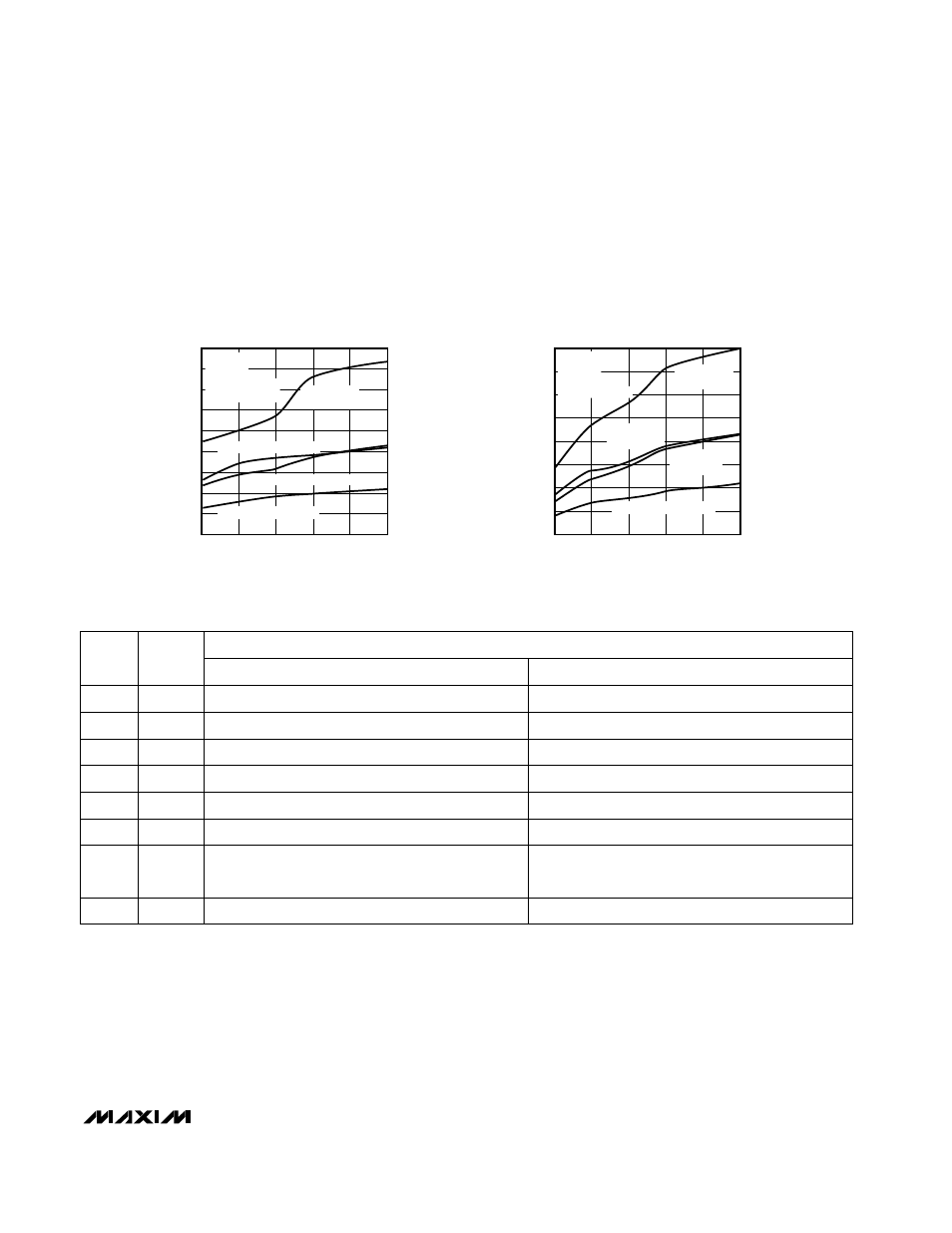
MAX861
OUTPUT CURRENT vs. CAPACITANCE
HIGH-FREQUENCY MODE
MAX860-10
CAPACITANCE (
µ
F)
OUTPUT CURRENT (mA)
4.7
40
20
1
2.2
22
60
10
10
30
50
V
IN
= +4.5V,
V
OUT
= -3.5V
V
IN
= +4.5V, V
OUT
= -4V
V
IN
= +3V, V
OUT
= -2.4V
V
IN
= +3V, V
OUT
= -2.7V
f
OSC
= 250kHz
FC = OUT
LV = GND
INVERTER MODE
80
70
0
0.33
MAX861
OUTPUT CURRENT vs. CAPACITANCE
MEDIUM-FREQUENCY MODE
MAX860-11
CAPACITANCE (
µ
F)
OUTPUT CURRENT (mA)
4.7
40
20
1
2.2
22
60
10
10
30
50
V
IN
= +4.5V,
V
OUT
= -3.5V
V
IN
= +3V,
V
OUT
= -2.4V
V
IN
= +4.5V,
V
OUT
= -4V
V
IN
= +3V, V
OUT
= -2.7V
f
OSC
= 100kHz
FC = GND
LV = GND
INVERTER MODE
______________________________________________________________Pin Description
____________________________Typical Operating Characteristics (continued)
(All curves generated using the inverter circuit shown in the
Typical Operating Circuits
with LV = GND and T
A
= +25°C, unless other-
wise noted. Test results also valid for doubler mode with LV = OUT and T
A
= +25°C. All capacitor values used are those recom-
mended in Table 3, unless otherwise noted. The output resistance curves represent the resistance of the device itself, which is R
O
in
the equation for R
OUT
shown in the
Capacitor Selection
section.)
INVERTER
DOUBLER
Doubled Positive Output
Flying-Capacitor Negative Terminal
Ground
Low-Voltage-Operation Input. Connect to OUT.
Active-Low Shutdown Input. Connect to GND pin if not
used. Connect to OUT to disable the charge pump.
Positive Input Supply
Flying-Capacitor Positive Terminal
Frequency Control, see Table 1
FUNCTION
Positive Input Supply
V
DD
8
Flying-Capacitor Negative Terminal
C1-
4
Negative Output
OUT
5
Low-Voltage-Operation Input. Connect to GND.
LV
6
Active-Low Shutdown Input. Connect to V
DD
if not
used. Connect to GND to disable the charge pump.
–
S
—
H
—
D
—
N
–
7
Ground
GND
3
Flying-Capacitor Positive Terminal
C1+
2
Frequency Control, see Table 1
FC
1
NAME
PIN