Electrical characteristics (continued) – Rainbow Electronics MAX861 User Manual
Page 3
MAX860/MAX861
50mA, Frequency-Selectable,
Switched-Capacitor Voltage Converters
_______________________________________________________________________________________
3
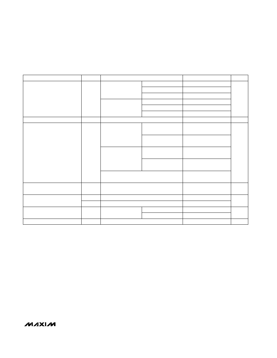
ELECTRICAL CHARACTERISTICS (continued)
(Typical Operating Circuit (Inverter), V
DD
= +5V,
–
S
—
H
—
D
—
N
–
= V
DD
, FC = LV = GND, C1 = C2 = 10µF (Note 2), T
A
= T
MIN
to T
MAX
, unless
otherwise noted. Typical values are at T
A
= +25°C.)
Note 2:
C1 and C2 are low-ESR (<0.2
Ω
) aluminum electrolytics. Capacitor ESR adds to the circuit’s output resistance. Using
capacitors with higher ESR may reduce output voltage and efficiency.
Note 3:
Specified output resistance includes the effect of the 0.2
Ω
ESR of the test circuit’s capacitors.
Note 4:
The switches are driven directly at the oscillator frequency, without any division.
Note 5:
At lowest frequencies, using 10µF capacitors gives worse efficiency figures than using the recommended capacitor
values in Table 3, due to larger 1 ⁄ (f
s
x C1) term in R
OUT
.
–
S
—
H
—
D
—
N
–
< 0.3V
MAX860
LV = GND
No load
MAX860/MAX861, FC = V
DD
,
I
L
= 50mA to GND, C1 = C2 = 68µF
MAX860,
FC = V
DD
MAX861,
FC = V
DD
MAX861
FC < 4V
CONDITIONS
µA
10
Shutdown Supply Current
1
V
0.3
V
IL
–
S
—
H
—
D
—
N
–
Threshold
1.2
V
IH
%
99
99.9
Voltage-Conversion Efficiency
%
87
Power Efficiency (Note 5)
88
92
93
96
80
130
30
50
3
6
90
93
93
96
8
13
60
100
kHz
160
250
f
S
Switching Frequency
(Note 4)
µA
-2
-4
I
FC
FC Current (from V
DD
)
UNITS
MIN
TYP
MAX
SYMBOL
PARAMETER
No load, V
OUT
= -4V
µs
500
Time to Exit Shutdown
FC = V
DD
FC = GND
FC = OUT
FC = V
DD
FC = GND
FC = OUT
R
L
= 2k
Ω
from V
DD
to OUT
R
L
= 1k
Ω
from OUT
to GND
R
L
= 2k
Ω
from V
DD
to OUT
R
L
= 1k
Ω
from OUT
to GND
MAX86_I/E
MAX86_M