Applications information, Table 1. low-esr capacitor manufacturers – Rainbow Electronics MAX871 User Manual
Page 6
MAX870/MAX871
Switched-Capacitor Voltage Inverters
6
_______________________________________________________________________________________
Conversion losses occur during the charge transfer
between C1 and C2 when there is a voltage difference
between them. The power loss is:
__________Applications Information
Capacitor Selection
To maintain the lowest output resistance, use capaci-
tors with low ESR (Table 1). The charge-pump output
resistance is a function of C1’s and C2’s ESR.
Therefore, minimizing the charge-pump capacitor’s
ESR minimizes the total output resistance.
Flying Capacitor (C1)
Increasing the flying capacitor’s size reduces the out-
put resistance. Small C1 values increase the output
resistance. Above a certain point, increasing C1’s
capacitance has a negligible effect, because the out-
put resistance becomes dominated by the internal
switch resistance and capacitor ESR.
Output Capacitor (C2)
Increasing the output capacitor’s size reduces the out-
put ripple voltage. Decreasing its ESR reduces both
output resistance and ripple. Smaller capacitance val-
ues can be used with light loads if higher output ripple
can be tolerated. Use the following equation to calcu-
late the peak-to-peak ripple:
Input Bypass Capacitor
Bypass the incoming supply to reduce its AC impedance
and the impact of the MAX870/MAX871’s switching
noise. The recommended bypassing depends on the cir-
cuit configuration and on where the load is connected.
When the inverter is loaded from OUT to GND, current
from the supply switches between 2 x I
OUT
and zero.
Therefore, use a large bypass capacitor (e.g., equal to
the value of C1) if the supply has a high AC impedance.
When the inverter is loaded from IN to OUT, the circuit
draws 2 x I
OUT
constantly, except for short switching
spikes. A 0.1µF bypass capacitor is sufficient.
Voltage Inverter
The most common application for these devices is a
charge-pump voltage inverter (Figure 1). This applica-
tion requires only two external components—capacitors
C1 and C2—plus a bypass capacitor, if necessary.
Refer to the
Capacitor Selection
section for suggested
capacitor types.
Cascading Devices
Two devices can be cascaded to produce an even
larger negative voltage (Figure 4). The unloaded output
voltage is normally -2 x V
IN
, but this is reduced slightly
by the output resistance of the first device multiplied by
the quiescent current of the second. When cascading
more than two devices, the output resistance rises dra-
matically. For applications requiring larger negative
voltages, see the MAX864 and MAX865 data sheets.
Paralleling Devices
Paralleling multiple MAX870s or MAX871s reduces the
output resistance. Each device requires its own pump
capacitor (C1), but the reservoir capacitor (C2) serves
all devices (Figure 5). Increase C2’s value by a factor
of n, where n is the number of parallel devices. Figure 5
shows the equation for calculating output resistance.
Combined Doubler/Inverter
In the circuit of Figure 6, capacitors C1 and C2 form the
inverter, while C3 and C4 form the doubler. C1 and C3
are the pump capacitors; C2 and C4 are the reservoir
V
=
I
f
x C2
RIPPLE
OUT
OSC
+
2
2
x I
x ESR
OUT
C
P
C1 V
V
C2 V
2V
V
x f
CONV.LOSS
IN
2
OUT
2
RIPPLE
2
OUT RIPPLE
OSC
[
]
/
/
=
−
+
−
1
2
1
2
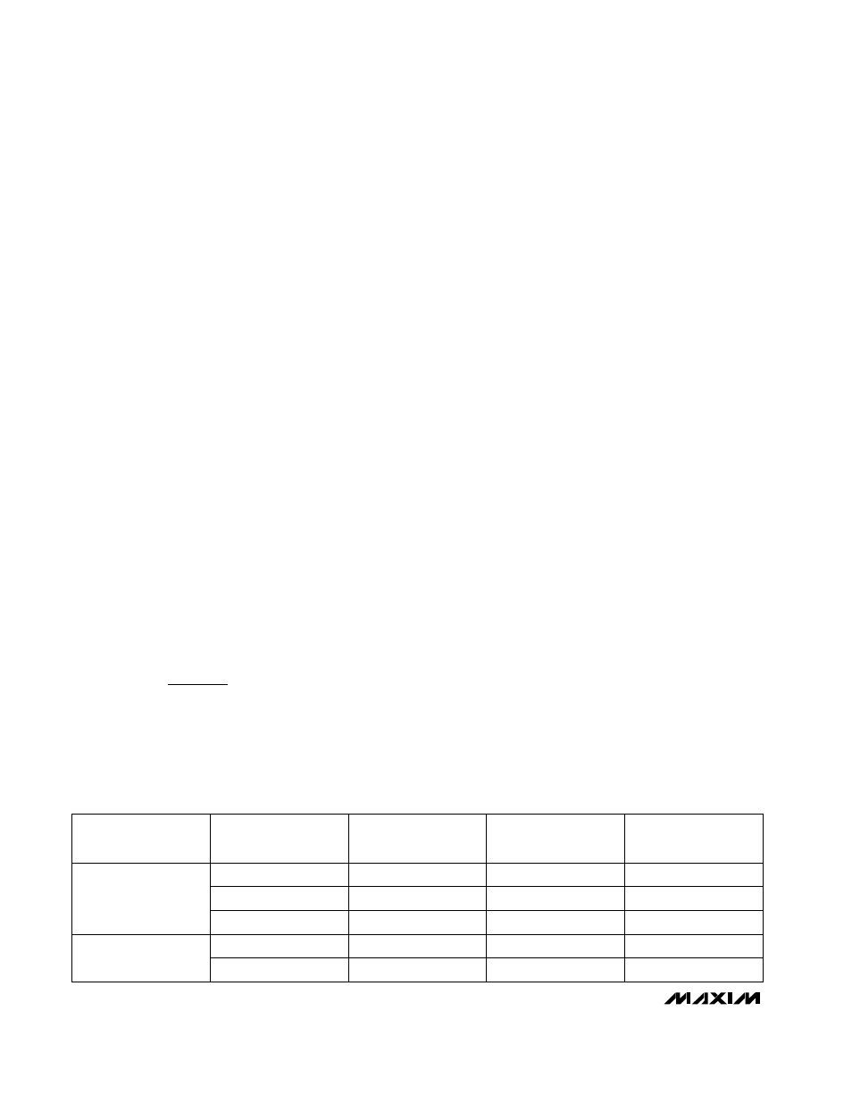
Table 1. Low-ESR Capacitor Manufacturers
Surface-Mount
Tantalum
PRODUCTION
METHOD
(714) 969-2491
(803) 946-0690
PHONE
(603) 224-1961
(603) 224-1430
(714) 960-6492
(803) 626-3123
FAX
MANUFACTURER
AVX
Matsuo
Sprague
SERIES
TPS series
267 series
593D, 595D series
(714) 969-2491
(803) 946-0690
AVX
Matsuo
(714) 960-6492
(803) 626-3123
X7R
X7R
Surface-Mount
Ceramic