Rainbow Electronics MAX1804 User Manual
Page 8
MAX1804
External Four-Input Feedback Integrator for
Power Supplies
8
_______________________________________________________________________________________
inputs are disabled, OUT is high impedance. Connect
any unused input to GND.
Setting the Maximum Regulator Output
Voltage Increase
The ratio between the maximum guaranteed OUT cur-
rent of 10µA and the current in the regulator’s feedback
resistive divider determines the maximum increase. The
maximum increase in the regulator output voltage
depends on the regulator’s upper feedback resistor
(R
TOP
) and the sink current into OUT:
∆V
OUT
(MAX) = I
OUT
(MAX) x R
TOP
The maximum adjust current I
OUT
(MAX) can be further
limited with a resistor (R
OUT
) between OUT and the
feedback point of the regulator (see Typical Operating
Circuit):
I
OUT
(MAX) = V
FB
/ R
OUT
where V
FB
is the voltage at the regulator’s feedback
point.
Therefore:
∆V
OUT
(MAX) = V
FB
x R
TOP
/ R
OUT
and:
R
OUT
= V
FB
x R
TOP
/
∆V
OUT
(MAX)
Place the regulator’s feedback resistors and R
OUT
close to the regulator’s feedback pin to reduce noise
pickup at the regulator’s feedback point, which can
cause unstable switching in the regulator (Figure 5).
Shutdown Mode
SHDN is a logic input that, when held low, places the
MAX1804 in its low-power shutdown mode, reducing
the supply current to 10nA (typ). The IN1–IN4, OUT,
and ADJ are high impedance when the MAX1804 is in
shutdown or when V+ is removed. Connect SHDN to
V+ for normal operation.
Undervoltage Lockout
The MAX1804 has an undervoltage lockout (UVLO) fea-
ture that deactivates the device when the supply volt-
age at V+ goes below 2.4V; IN1–IN4, OUT, and ADJ go
to high impedance and do not affect the regulator oper-
ation. Hysteresis holds the device in lockout until the
supply voltage at V+ rises above 2.6V.
Integrator Gain-Bandwidth Product
and Regulator Stability
The MAX1804 gain-bandwidth (GBW) product is set by
the external capacitor on COMP:
GBW = [4 x (IN_ transconductance)] / (2
π
✕
C
COMP
)
The bandwidth is typically 40kHz with a 470pF capaci-
tor on COMP.
For system stability, the integrator GBW product is typi-
cally set below the regulator circuit’s crossover frequen-
cy, if known. Switching regulators typically have
crossover frequencies well below their switching frequen-
cies. Setting the MAX1804’s GBW product too high can
cause regulator loop instability, typically evidenced by
ringing after transients. Setting the GBW product unnec-
essarily low will slow the MAX1804’s loop response to
transients, although the regulator’s loop transient
response will remain unaffected (see Load Transient
Response in Typical Operating Characteristics).
Often the regulator’s crossover frequency varies with
load and is not easily found. If the regulator’s crossover
frequency is unknown, the MAX1804’s gain-bandwidth
product can be chosen empirically. Start with a fairly
low capacitor value (470pF is a good starting point)
and increase the value until the circuit is stable with all
loads. Then increase the value further to ensure design
margin. If transient response is unimportant, choose a
large COMP capacitor value (such as 2200pF), thereby
maximizing stability.
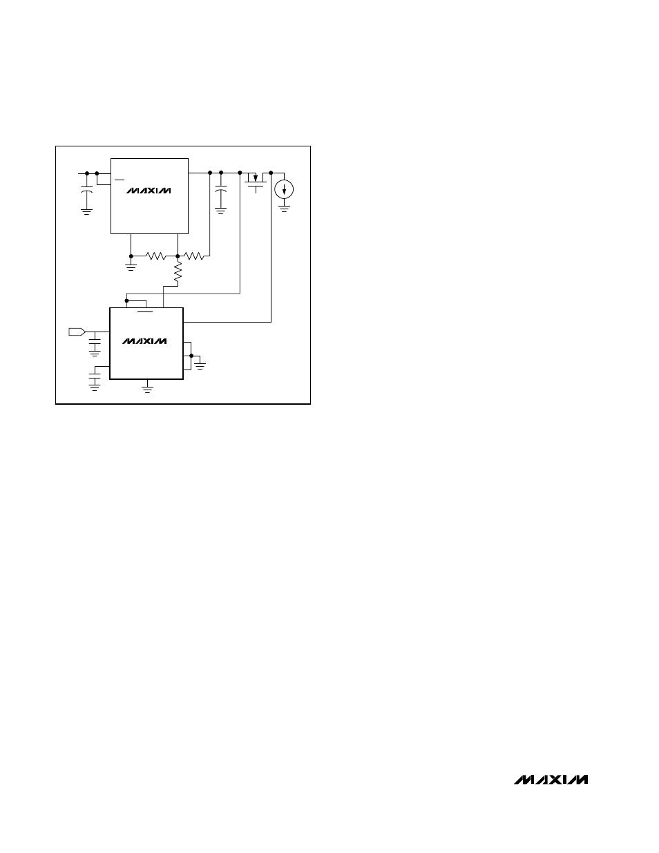
Figure 3. MAX1804 Used with Linear Regulator
COMP
ADJ
IN2
IN3
IN4
IN1
GND
V+
SET
10
µF
2200pF
R
TOP
300k
R
TOP
600k
I
LOAD
0 TO
500mA
FDV 304P
5V TO
11V
1.25V
REFERENCE
MAX1804
SHDN
10
µF
R
BOTTOM
100k
GND
SET
OUT
IN
MAX603
OFF