Rainbow Electronics MAX786 User Manual
Page 11
MAX786
Dual-Output Power-Supply
Controller for Notebook Computers
______________________________________________________________________________________
11
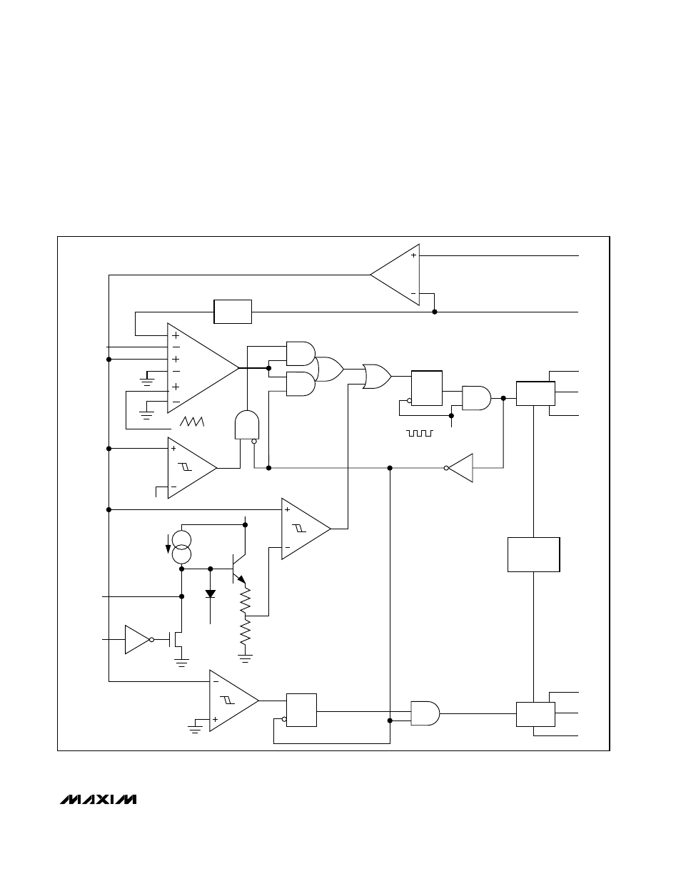
second half-cycle, the PWM turns on the high-side
MOSFET by connecting the capacitor to the MOSFET
gate by closing an internal switch between BST_ and
DH_. This provides the necessary enhancement voltage
to turn on the high-side switch, an action that “boosts”
the 5V gate-drive signal above the battery voltage.
Ringing seen at the high-side MOSFET gates (DH3 and
DH5) in discontinuous-conduction mode (light loads) is
a natural operating condition caused by the residual
energy in the tank circuit formed by the inductor and
stray capacitance at the LX_ nodes. The gate driver
negative rail is referred to LX_, so any ringing there is
directly coupled to the gate-drive supply.
1X
CS_
FB_
BST_
DH_
LX_
LEVEL
SHIFT
VL
SHOOT-
THROUGH
CONTROL
DL_
PGND
LEVEL
SHIFT
Q
R
S
SYNCHRONOUS
RECTIFIER CONTROL
N
3.3V
1R
30R
VL
4
µ
A
0mV TO 100mV
CURRENT
LIMIT
MINIMUM
CURRENT
(IDLE MODE)
25mV
SLOPE COMP
Σ
REF, 3.3V
(OR INTERNAL
5V REFERENCE)
MAIN PWM
COMPARATOR
60kHz
LPF
R
S
Q
OSC
SS_
ON_
Figure 3. PWM Controller Block Diagram