Pin descriptions – Rainbow Electronics MAX903 User Manual
Page 7
MAX900–MAX903
High-Speed, Low-Power Voltage Comparators
_______________________________________________________________________________________
7
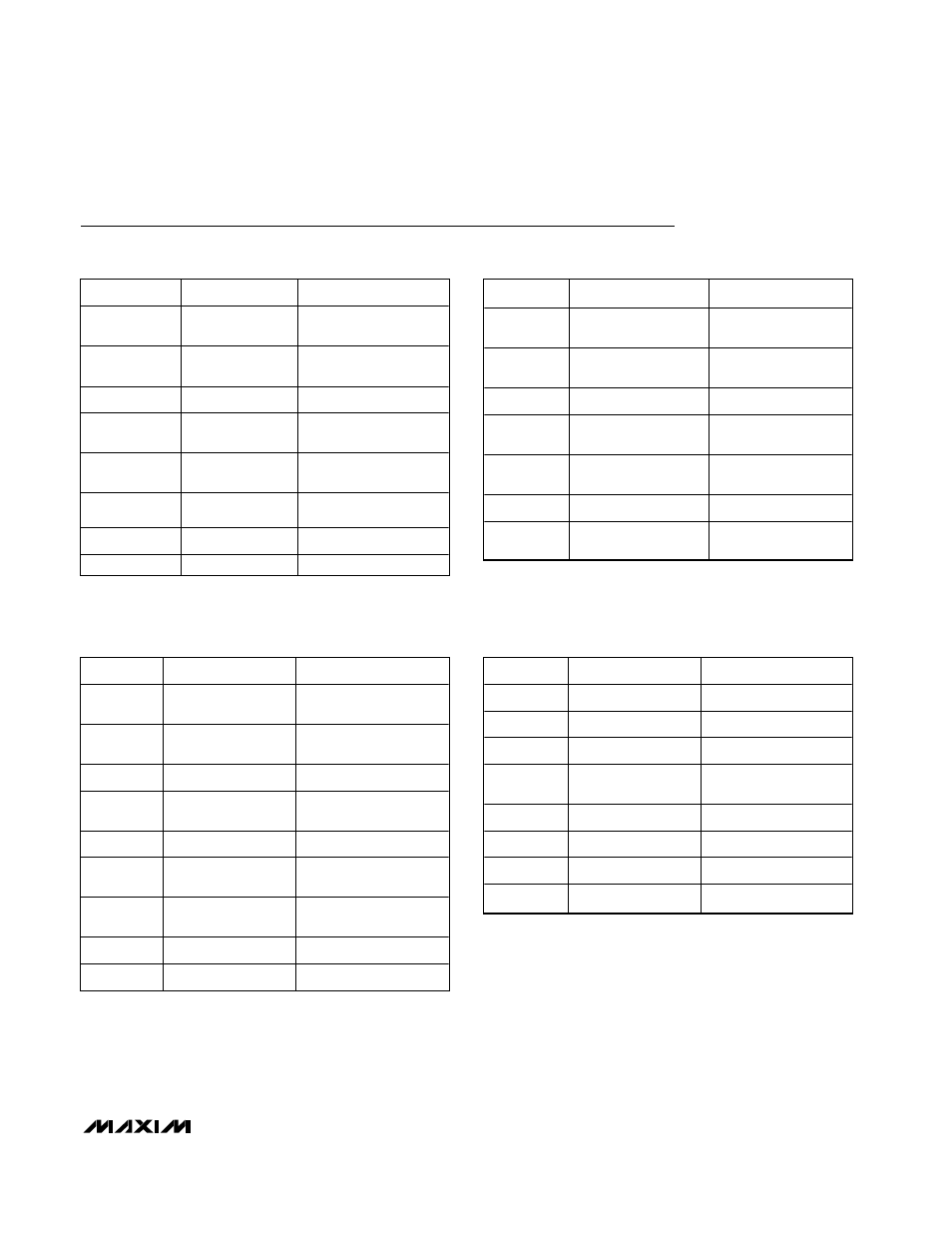
PIN
NAME
FUNCTION
1, 10, 11, 20
IN- (A, B, C, D)
Negative Input
(Channels A, B, C, D)
2, 9, 12, 19
IN+ (A, B, C, D)
Positive Input
(Channels A, B, C, D)
3
GND
Ground Terminal
4, 7, 14, 17
LATCH (A, B, C,
D)
Latch Input (Channels
A, B, C, D)
5, 6, 15, 16
OUT (A, B, C, D)
Output (Channels A, B,
C, D)
8
V
EE
Negative Analog
Supply and Substrate
13
V
DD
Positive Digital Supply
18
V
CC
Positive Analog Supply
PIN
NAME
FUNCTION
1, 8
IN- (A, B)
Negative Input
(Channels A, B)
2, 9
IN+ (A, B)
Positive Input
(Channels A, B)
3
GND
Ground Terminal
4, 11
LATCH (A, B)
Latch Input (Channels
A, B)
5, 12
OUT (A, B)
Output (Channels A, B)
6, 13
N.C.
No Connection. Not
internally connected.
7
V
EE
Negative Analog
Supply and Substrate
10
V
DD
Positive Digital Supply
14
V
CC
Positive Analog Supply
PIN
NAME
FUNCTION
1
V
CC
Positive Analog Supply
2
IN+
Positive Input
3
IN-
Negative Input
4
V
EE
Negative Analog
Supply and Substrate
5
LATCH
Latch Input
6
GND
Ground Terminal
7
OUT
Output
8
V
DD
Positive Digital Supply
PIN
NAME
FUNCTION
1, 8, 9, 16
IN- (A, B, C, D)
Negative Input
(Channels A, B, C, D)
2, 7, 10, 15
IN+ (A, B, C, D)
Positive Input
(Channels A, B, C, D)
3
GND
Ground Terminal
4, 5, 12, 13
OUT (A, B, C, D)
Output (Channels A,
B, C, D)
6
V
EE
Negative Analog
Supply and Substrate
11
V
DD
Positive Digital Supply
14
V
CC
Positive Analog
Supply
Pin Descriptions
MAX900
MAX901
MAX902
MAX903