Typical operating characteristics (continued), Pin description – Rainbow Electronics MAX1574 User Manual
Page 5
MAX1574
180mA, 1x/2x, White LED Charge Pump
in 3mm x 3mm TDFN
_______________________________________________________________________________________
5
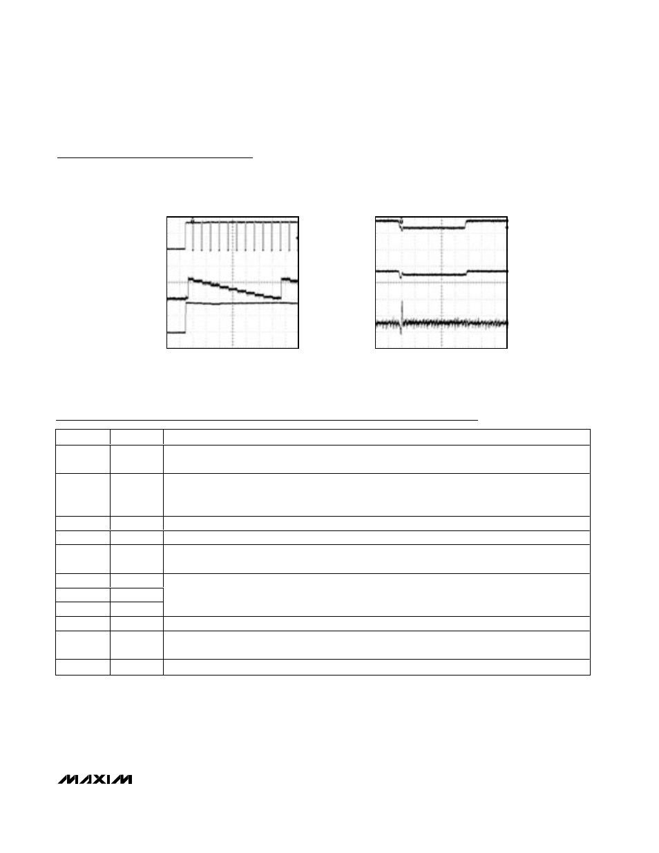
Typical Operating Characteristics (continued)
(Circuit of Figure 2, V
IN
= 3.6V, EN = IN, driving three white LEDs, T
A
= +25°C, unless otherwise noted.)
DIMMING RESPONSE
MAX1574 toc10
I
OUT
V
EN
V
OUT
50mA/div
2V/div
2V/div
10ms/div
LINE TRANSIENT 3.8V TO 3.3V TO 3.8V
MAX1574 toc11
V
OUT
V
IN
I
OUT
1V/div
1V/div
60mA,
20mA/div
100µs/div
Pin Description
PIN
NAME
FUNCTION
1
IN
Supply Voltage Input. Connect a 0.47µF to 1µF ceramic capacitor from IN to GND. The input voltage
range is 2.7V to 5.5V. IN is high impedance during shutdown.
2
EN
Enable and Dimming Control. Pulsing EN low dims the LEDs in multiple steps. Drive low for longer than
2ms (typ) to shut down the IC. From shutdown, drive EN high (50µs min) to set I
LED
to the maximum
current (see the SETfunction). Pulse EN low for 0.5µs to 500µs to dim the LEDs (Figure 1).
3
CP
Transfer-Capacitor Positive Connection. Connect a 0.22µF capacitor from CP to CN.
4
CN
Transfer-Capacitor Negative Connection. Connect a 0.22µF capacitor from CP to CN.
5
SET
Current-Set Input. Connect a resistor (R
SET
) from SET to GND to set the maximum LED current.
I
LED(MAX)
= 393
×
0.6V / R
SET
. SET is internally biased to 0.6V. SET is high impedance during shutdown.
6
LED3
7
LED2
8
LED1
LED_ Cathode Connection. Current flowing into LED_ is based on SET description above. In 2x mode,
the charge pump regulates the lowest LED_ voltage to 0.18V. Connect LED_ to IN for unpopulated LEDs.
LED_ is high impedance during shutdown.
9
GND
Ground. Connect GND to system ground and as close as possible to the input-bypass capacitor ground.
10
OUT
Output. Connect a 0.47µF to 1µF ceramic capacitor from OUT to GND, and connect OUT to the anodes
of all the LEDs. OUT is pulled to ground through an internal 5k
Ω
resistor in
shutdown.
—
EP
Exposed Paddle. Connect the exposed paddle directly to GND underneath the IC.