Detailed description, Voltage regulator – Rainbow Electronics MAX1873 User Manual
Page 9
Detailed Description
The MAX1873 includes all of the functions necessary to
charge 2-, 3-, or 4-series cell lithium-ion (Li+) battery
packs. It includes a high-efficiency step-down DC-DC
converter that controls charging voltage and current. It
also features input source current limiting so that an AC
adapter that supplies less than the total system current
in addition to charging current can be used without fear
of overload.
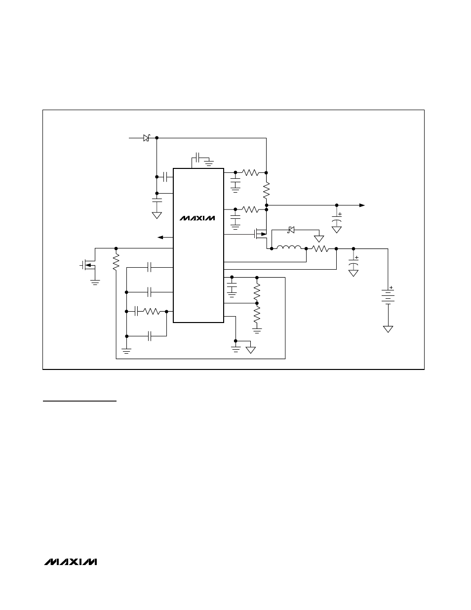
The DC-DC converter uses an external P-channel MOS-
FET switch, inductor, and diode to convert the input volt-
age to charging current or charging voltage. The typical
application circuit is shown in Figure 1. Charging current
is set by R
CSB
, while the battery voltage is measured at
BATT. The battery regulation voltage limit is nominally
set to 8.4V for the R version (2-cells), 12.6V for the S
version (3-cells), and 16.8V for the T version (4-cells),
but it can also be adjusted to other voltages for differ-
ent Li+ chemistries.
Voltage Regulator
Li+ batteries require a high-accuracy voltage limit while
charging. The battery regulation voltage is nominally
set to 4.2V per cell and can be adjusted ±5.25% by
setting the voltage at VADJ between REF and ground.
By limiting the adjust range of the regulation voltage, an
overall voltage accuracy of better than ±0.75% is main-
tained while using 1% resistors.
An internal error amplifier maintains voltage regulation
to within ±0.75%. The amplifier is compensated at CCV
(see Figure 1). Individual compensation of the voltage
regulation and current regulation loops allows for opti-
mal compensation of each. A typical CCV compensa-
tion network is shown in Figure 1 and will suffice for
most designs.
MAX1873
Simple Current-Limited Switch-Mode
Li+ Charger Controller
_______________________________________________________________________________________
9
MAX1873
GND
VADJ
REF
ICHG/EN
IOUT
DCIN
VH
VL
CSSP
CSSN
VIN 17V TO 28V
(9V MIN FOR 2- CELLS)
4V OUT PER
200mV ON R
CSB
EXT
BATT
CSB
CCI
CCS
CCV
D1
MBR5340
C
VL
2.2
µF
R
P
4.7
Ω
C
P
0.01
µF
R
N
4.7
Ω
C
N
0.01
µF
P
R
CSS
0.033
Ω
D2
MBR5340
SYSTEM
LOAD
C
L
47
µF
C
BATT
68
µF
LI+
BATTERY
(2- TO 4-CELLS)
R
CSB
0.068
Ω
L1
10
µH
R1
R2
C
REF
1
µF
C
CCVP
1nF
R
CCV
10k
Ω
C
CCVS
0.1
µF
C
CCS
47nF
C
CC
47nF
N
DISABLE
C
DCIN
0.22
µF
C
VH
0.22
µF
100k
Ω
Figure 1. Typical Application Circuit