Step-down dc-dc controllers – Rainbow Electronics MAX652 User Manual
Page 9
MAX649/MAX651/MAX652
5V/3.3V/3V or Adjustable, High-Efficiency,
Low I
Q
, Step-Down DC-DC Controllers
_______________________________________________________________________________________
9
inductor, and the control circuit adjusts the switch duty
cycle to maintain regulation without exceeding the
switch current capability (Figure 3a). This provides
excellent load-transient response and high efficiency.
In discontinuous-conduction mode (DCM), current
through the inductor starts at zero, rises to a peak
value, then ramps down to zero. Although efficiency is
still excellent, the output ripple increases slightly, and
the switch waveforms exhibit ringing (the self-resonant
frequency of the inductor). This ringing is to be expect-
ed and poses no operational problems.
Dropout
The MAX649/MAX651/MAX652 are said to be in
dropout when the input voltage (V+) is low enough
that the output drops below the minimum output
voltage specification (see
Electrical Characteristics).
The dropout voltage is the difference between the
input and output voltage when dropout occurs.
See the
Typical Operating Characteristics for the
Dropout Voltage vs. Load Current and Dropout Voltage
vs. Temperature graphs.
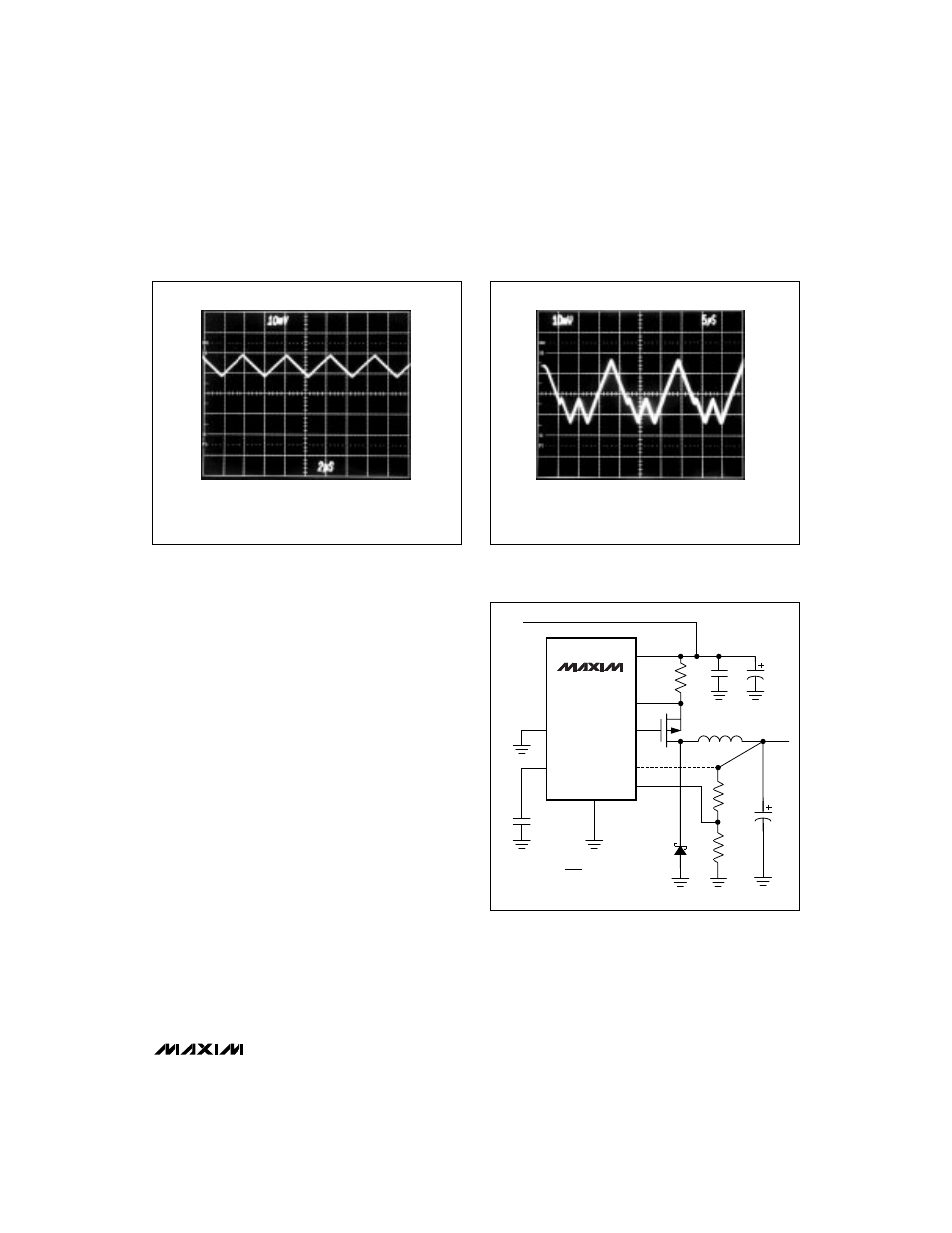
V+ = 10V, I
LOAD
= 1.3A
CIRCUIT OF FIGURE 1, R1 = 150m
Ω
1.5A
0A
1A
2
µ
s/div
Figure 3a. MAX649 Continuous-Conduction Mode, Heavy
Load-Current Waveform (500mA/div)
V+ = 10V, I
LOAD
= 1.4A
CIRCUIT OF FIGURE 1, R1 = 100m
Ω
2.5A
0A
1.5A
0.5A
1.0A
2.0A
5
µ
s/div
Figure 3b. MAX649 Light/Medium Load-Current Waveform
(500mA/div)
(
)
MAX649
MAX651
MAX652
V+
CS
GND
5
6
2
8
3
V
IN
C2
330
µ
F
7
1
EXT
OUT
SHDN
4
C3
0.1
µ
F
C4
0.1
µ
F
C1
100
µ
F
R1
0.1
Ω
D1
1N5820
L1
22
µ
H
P1
Si9430
OUTPUT
@ 1.5A
REF
FB
R2
R3
150k
R2 = R3
V
OUT
V
REF
– 1
V
REF
= 1.5V
Figure 4. Adjustable-Output Operation