Step-down dc-dc controllers – Rainbow Electronics MAX652 User Manual
Page 12
MAX649/MAX651/MAX652
5V/3.3V/3V or Adjustable, High-Efficiency,
Low I
Q
, Step-Down DC-DC Controllers
12
______________________________________________________________________________________
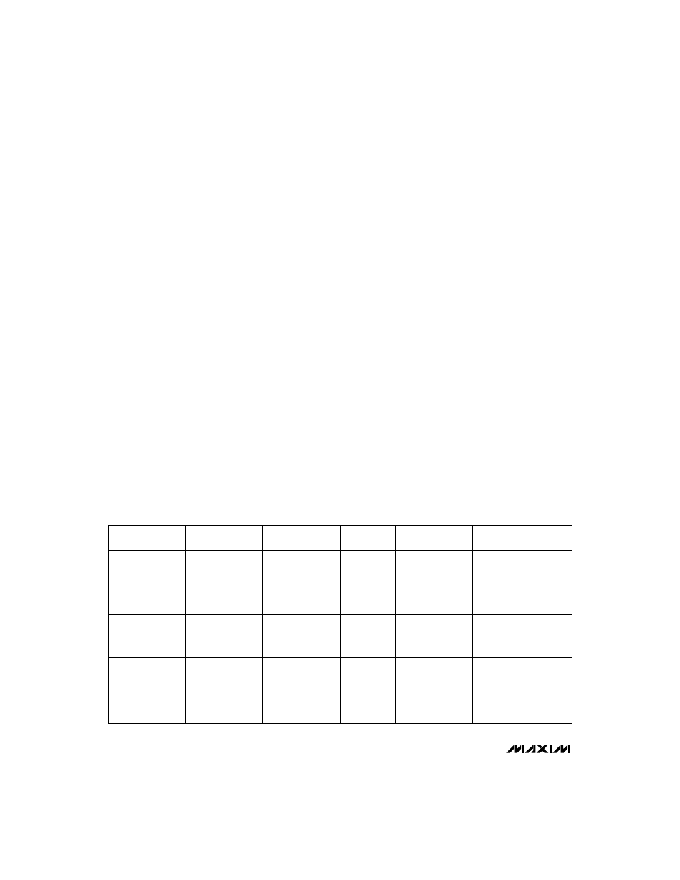
Table 1. Component Selection Guide
PRODUCTION
METHOD
INDUCTORS
CAPACITORS
DIODES
CURRENT-SENSE
RESISTORS
MOSFETS
Surface Mount
Matsuo
267 series
Sprague
595D series
Nihon
NSQ series
IRC
LRC series
Miniature
Through-Hole
Sumida
RCH855-220M
Sanyo
OS-CON series
low-ESR organic
semiconductor
IRC
OAR series
Motorola
Low-Cost
Through-Hole
Renco
RL 1284-22
Motorola
1N5820,
1N5823
Motorola
TMOS power MOSFETs
Sumida
CDR125-220 (22µH)
Coiltronics
CTX 100 series
Siliconix
Little Foot series
Motorola
medium-power
surface-mount products
Nichicon
PL series
low-ESR electrolytics
United Chemi-Con
LXF series
a drain-to-source rating of -20V and a typical on-resis-
tance of 0.115
Ω
at 2A with V
GS
= -4.5V. Tables 1 and 2
list suppliers of switching transistors suitable for use
with these devices.
Capacitor Selection
Output Filter Capacitor
The primary criterion for selecting the output filter
capacitor is low equivalent series resistance (ESR),
rather than high capacitance. An electrolytic capacitor
with low enough ESR will automatically have high
enough capacitance. The product of the inductor-cur-
rent variation and the ESR of the output filter capacitor
determines the amplitude of the high-frequency ripple
seen on the output voltage. When a 330µF, 10V
Sprague surface-mount capacitor (595D series) with
ESR = 0.15
Ω
is used, 40mV of output ripple is typically
observed when stepping down from 10V to 5V at 1A.
The output filter capacitor's ESR also affects efficiency.
Use low-ESR capacitors for best performance. The
smallest low-ESR SMT tantalum capacitors currently
available are from the Sprague 595D series. Sanyo OS-
CON organic semiconductor through-hole capacitors
and the Nichicon PL series also exhibit very low ESR.
Table 1 lists some suppliers of low-ESR capacitors.
Input Bypass Capacitor
The input bypass capacitor reduces peak currents
drawn from the voltage source, and also reduces the
amount of noise at the voltage source caused by the
switching action of the MAX649/MAX651/MAX652.
The input voltage source impedance determines the
size of the capacitor required at the V+ input. As
with the output filter capacitor, a low-ESR capacitor
is recommended. Bypass the IC separately with a
0.1µF ceramic capacitor placed close to the V+ and
GND pins.
Reference Capacitor
Bypass REF with a 0.1µF or larger capacitor. REF can
source at least 100µA.
Layout Considerations
Proper PC board layout is essential because of high
current levels and fast switching waveforms that radiate
noise. Minimize ground noise by connecting the anode
of the catch diode, the input bypass capacitor ground
lead, and the output filter capacitor ground lead to a
single point (“star” ground configuration). A ground
plane is recommended. Also minimize lead lengths to
reduce stray capacitance, trace resistance, and radiat-
ed noise. In particular, the traces connected to FB (if an
external resistor divider is used) and EXT must be
short. Place the 0.1µF ceramic bypass capacitor as
close as possible to V+ and GND.