Typical operating characteristics (continued), Pin description – Rainbow Electronics MAX1205 User Manual
Page 6
MAX1205
+5V Single-Supply, 1Msps, 14-Bit
Self-Calibrating ADC
6
_______________________________________________________________________________________
0
-105
-120
-135
-90
-75
-60
-45
-30
-15
0
200
100
300
400
500
600
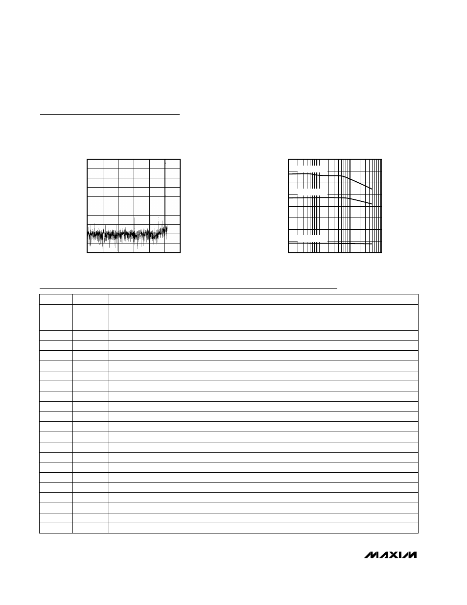
TYPICAL FFT
(f
IN
= 504.5kHz, 2048 VALUE RECORD)
MAX1205-09
FREQUENCY (kHz)
AMPLITUDE (dBFS)
Typical Operating Characteristics (continued)
(AV
DD
= +5V ±5%, DV
DD
= DRV
DD
= +3.3V, V
RFPS
= +4.096V, V
RFNS
= AGND, V
CM
= +2.048V, differential input, f
CLK
= 2.048MHz,
calibrated, T
A
= +25°C, unless otherwise noted.)
1
1000
100
10
EFFECTIVE NUMBER OF BITS
vs. INPUT FREQUENCY
MAX1205-10
INPUT FREQUENCY (kHz)
ENOB (Bits)
10.0
10.5
11.0
11.5
12.0
12.5
13.0
13.5
14.0
A
IN
= -0.5dBFS
A
IN
= -6dBFS
A
IN
= -20dBFS
Pin Description
PIN
Digital Input to Start Calibration.
ST_CAL = 0: Normal conversion mode.
ST_CAL = 1: Start self-calibration.
ST_CAL
1
FUNCTION
NAME
Analog Ground
AGND
2, 4, 5
Data Out-of-Range Bit
DOR
7
Analog Power Supply, +5V ±5%
AV
DD
3, 6
Bit 12
D12
9
Bit 10
D10
11
Bit 11
D11
10
Bit 13 (MSB)
D13
8
Bit 8
D8
13
Bit 6
D6
15
Bit 7
D7
14
Digital Ground
DGND
17, 28, 29
Bit 4
D4
19
Bit 5
D5
18
Digital Power Supply for the Output Drivers, +3V to +5.25V, DRV
DD
≤
DV
DD
DRV
DD
16
Bit 9
D9
12
Bit 2
D2
21
Bit 3
D3
20
Bit 0 (LSB)
D0
23
Bit 1
D1
22
Test Pin 3.
Leave unconnected.
TEST3
24