Chip information, Package information, Table 2. power-supply voltage combinations – Rainbow Electronics MAX1205 User Manual
Page 12
MAX1205
+5V Single-Supply, 1Msps, 14-Bit
Self-Calibrating ADC
Maxim cannot assume responsibility for use of any circuitry other than circuitry entirely embodied in a Maxim product. No circuit patent licenses are
implied. Maxim reserves the right to change the circuitry and specifications without notice at any time.
12
____________________Maxim Integrated Products, 120 San Gabriel Drive, Sunnyvale, CA 94086 408-737-7600
© 1998 Maxim Integrated Products
Printed USA
is a registered trademark of Maxim Integrated Products.
First, a multilayer printed circuit board (PCB) with sepa-
rate ground and power-supply planes is recommend-
ed. Run high-speed signal traces directly above the
ground plane. Since the MAX1205 has separate analog
and digital ground buses (AGND and DGND respec-
tively), the PCB should also have separate analog and
digital ground sections connected at only one point
(star ground). Digital signals should run above the digi-
tal ground plane and analog signals should run above
the analog ground plane. Digital signals should be kept
far away from the sensitive analog inputs, reference
inputs senses, common-mode input, and clock input.
The MAX1205 has three power-supply inputs: analog
V
DD
(AV
DD
), digital V
DD
(DV
DD
), and drive V
DD
(DRV
DD
).
Each AV
DD
input should be decoupled with parallel
ceramic-chip capacitors of values 0.1µF and 0.001µF,
with these capacitors as close to the pin as possible and
with the shortest possible connection to the ground
plane. The DV
DD
pins should also have separate 0.1µF
capacitors adjacent to their respective pins, as should the
DRV
DD
pin. Minimize the digital load capacitance.
However, if the total load capacitance on each digital out-
put exceeds 20pF, the DRV
DD
decoupling capacitor
should be increased or, preferably, digital buffers should
be added.
The power-supply voltages should be decoupled with
large tantalum or electrolytic capacitors at the point
they enter the PCB. Ferrite beads with additional
decoupling capacitors forming a pi-network may
improve performance.
The analog power-supply input (AV
DD
) for the
MAX1205 is typically +5V while the digital supplies can
vary from +5V to +3V. Usually, DV
DD
and DRV
DD
pins
are connected to the same power supply. Note that the
DV
DD
supply voltage must be greater than or equal to
the DRV
DD
voltage. For example, a digital +3.3V supply
could be connected to DRV
DD
while a cleaner +5V
supply is connected to DV
DD
, resulting in slightly
improved performance. Alternatively, the +3.3V supply
could be connected to both DRV
DD
and DV
DD
.
However, the +3.3V supply should not be connected to
DV
DD
while the +5V supply is connected to DRV
DD
(Table 2).
Table 2. Power-Supply Voltage Combinations
___________________Chip Information
TRANSISTOR COUNT: 56,577
SUBSTRATE CONNECTED TO: AGND
AV
DD
(V)
ALLOWED/NOT ALLOWED
Allowed
+5
Allowed
Not Allowed
+5
+5
Allowed
DRV
DD
(V)
+3.3
+5
+5
+5
+3.3
DV
DD
(V)
+3.3
+5
+3.3
+5
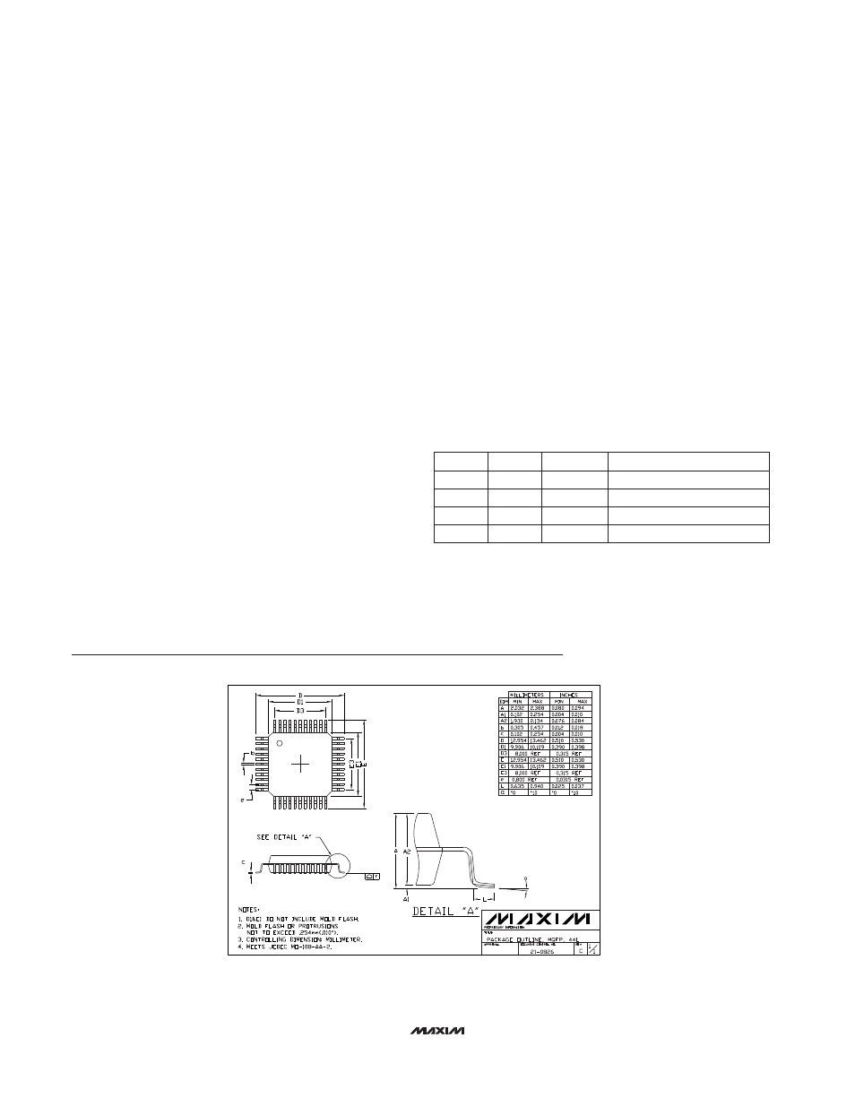
Package Information
MQFP44.EPS