Shutdown mode, Charge-pump output, Efficiency considerations – Rainbow Electronics MAX1721 User Manual
Page 6
MAX1719/MAX1720/MAX1721
SOT23, Switched-Capacitor
Voltage Inverters with Shutdown
6
_______________________________________________________________________________________
Charge-Pump Output
The MAX1719/MAX1720/MAX1721 are not voltage reg-
ulators: the charge pumps’ output resistance is
approximately 23
Ω
at room temperature (with V
IN
=
+5V), and V
OUT
approaches -5V when lightly loaded.
V
OUT
will droop toward GND as load current increases.
The droop of the negative supply (V
DROOP-
) equals the
current draw from OUT (I
OUT
) times the negative con-
verter’s output resistance (R
O
):
V
DROOP-
= I
OUT
·
R
O
The negative output voltage will be:
V
OUT
= -(V
IN
- V
DROOP-
)
Efficiency Considerations
The power efficiency of a switched-capacitor voltage
converter is affected by three factors: the internal loss-
es in the converter IC, the losses in the power switches,
and the resistive losses of the pump capacitors. The
total power loss is:
The internal losses are associated with the IC’s internal
functions, such as driving the switches, oscillator, etc.
These losses are affected by operating conditions such
as input voltage, temperature, and frequency.
The other two losses are associated with the voltage
converter circuit’s output resistance. Switch losses
occur because of the on-resistance of the MOSFET
switches in the IC. Charge-pump capacitor losses
occur because of their ESR. The relationship between
these losses and the output resistance is as follows:
where f
OSC
is the oscillator frequency. The first term is
the effective resistance from an ideal switched-
capacitor circuit. See Figures 3a and 3b.
Shutdown Mode
The MAX1719/MAX1720/MAX1721 have a logic-con-
trolled shutdown input. Driving SHDN low places the
MAX1720/MAX1721 in a low-power shutdown mode.
The MAX1719’s shutdown input is inverted from that of
the MAX1720/MAX1721. Driving SHDN high places the
MAX1719 in a low-power shutdown mode. The charge-
pump switching halts, supply current is reduced to
1nA, and OUT is actively pulled to ground through a 4
Ω
resistance.
P
+ P
= I
R
R
1
f
C1
2R
4ESR
ESR
SWITCH LOSSES
PUMP CAPACITOR LOSSES
OUT
2
O
O
OSC
SWITCHES
C1
C2
⋅
⋅
≅
( )
+
+
+
Σ
P
= P
+P
+P
LOSS
INTERNAL LOSSES
SWITCH LOSSES
PUMP CAPACITOR LOSSES
S1
IN
S2
S3
S4
C1
C2
V
OUT
= -(V
IN
)
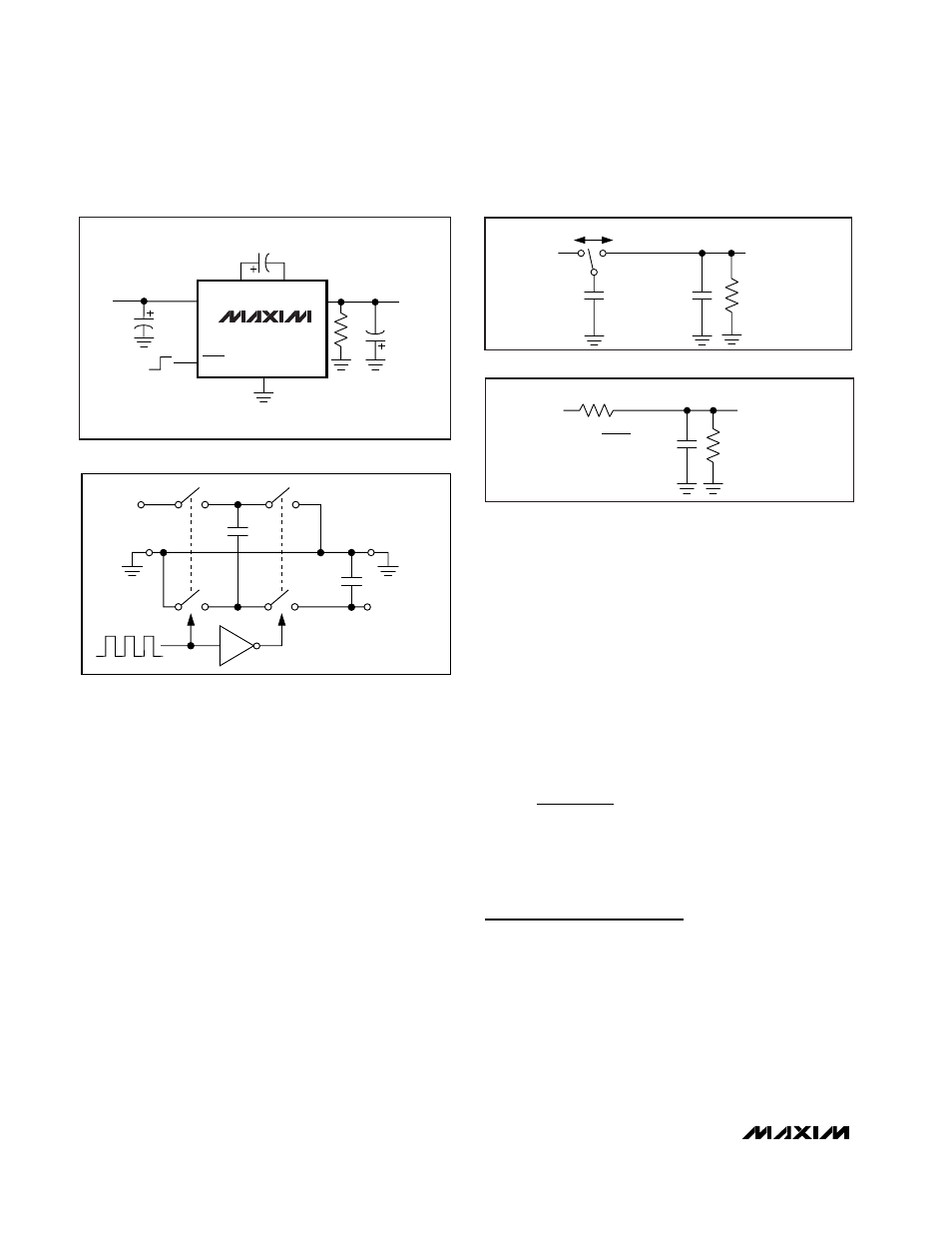
Figure 2. Ideal Voltage Inverter
V+
C1
f
C2
R
L
V
OUT
Figure 3a. Switched-Capacitor Model
R
EQUIV
=
R
EQUIV
V
OUT
R
L
1
V+
f
×
C1
C2
Figure 3b. Equivalent Circuit
NOTE: ( ) CAPACITORS ARE FOR MAX1720.
*ON/OFF POLARITY OF SHDN IS REVERSED FOR MAX1719.
C1
1
µ
F (10
µ
F)
C2
1
µ
F (10
µ
F)
2
1
5
ON
OFF
3
R
L
6
4
C3
1
µ
F (10
µ
F)
C1+
C1-
IN
SHDN
OUT
GND
INPUT
1.5V to 5.5V
NEGATIVE
OUTPUT
-1
·
V
IN
25mA
MAX1719*
MAX1721
Figure 1. Typical Application Circuit