2a pwm dc-dc step-down converters – Rainbow Electronics MAX1557 User Manual
Page 8
As the load current decreases, the converters enter a
pulse-skip mode in which the PWM comparator is dis-
abled. At light loads, efficency is enhanced by a
pulse-skip mode in which switching occurs only as
needed to service the load. Quiescent current in skip
mode is typically 16µA. See the Light-Load Switching
Waveforms and Load Transient graphs in the Typical
Operating Characteristics.
Load-Transient Response/
Voltage Positioning
The MAX1556/MAX1557 match the load regulation to
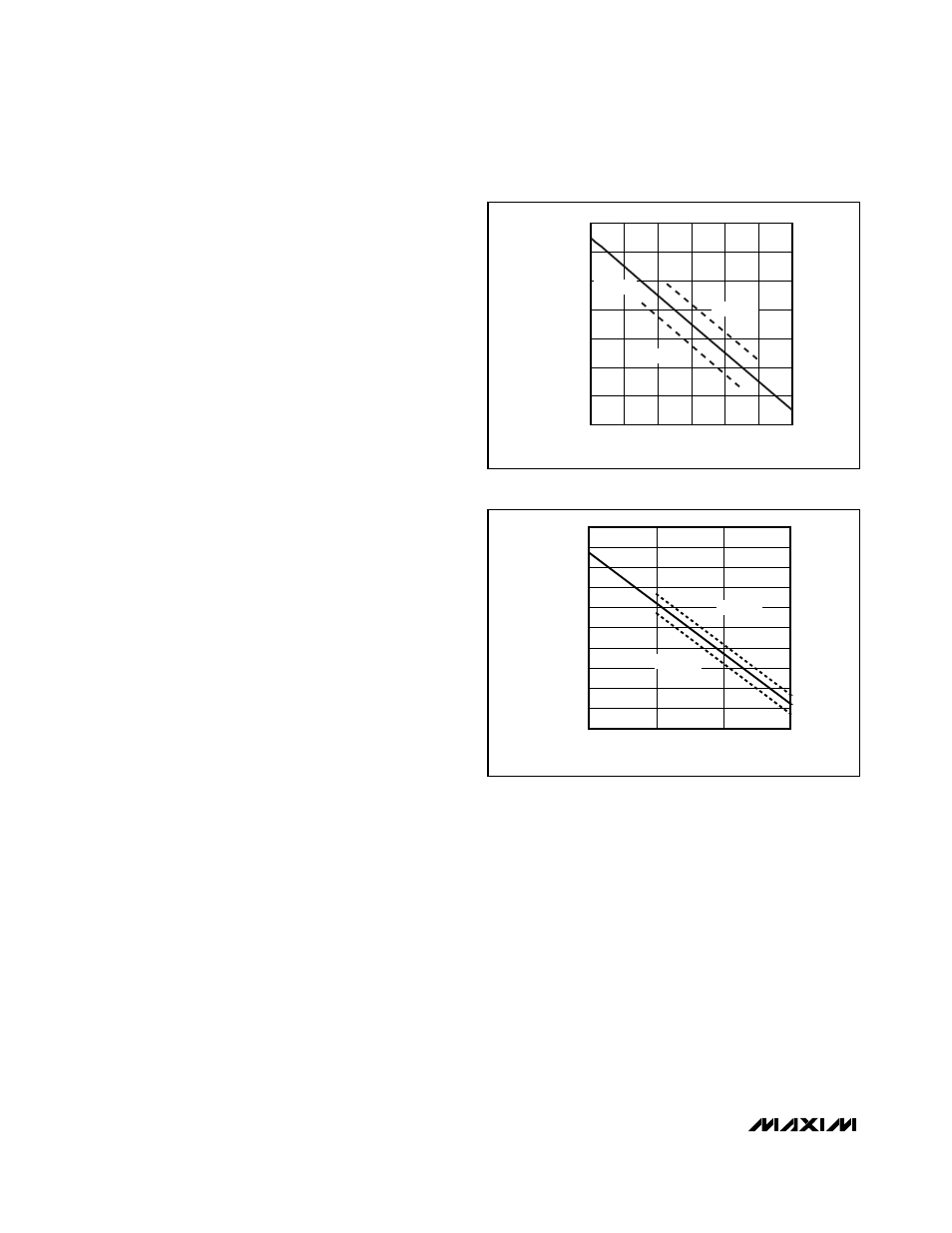
the voltage droop seen during transients. This is some-
times called voltage positioning. The load line used to
achieve this behavior is shown in Figures 4 and 5. There
is minimal overshoot when the load is removed and min-
imal voltage drop during a transition from light load to
full load. Additionally, the MAX1556 and MAX1557 use a
wide-bandwidth feedback loop to respond more quickly
to a load transient than regulators using conventional
integrating feedback loops (see Load Transient in the
Typical Operating Characteristics).
The MAX1556/MAX1557 use of a wide-band control
loop and voltage positioning allows superior load-tran-
sient response by minimizing the amplitude and dura-
tion of overshoot and undershoot in response to load
transients. Other DC-DC converters, with high gain-
control loops, use external compensation to maintain
tight DC load regulation but still allow large voltage
droops of 5% or greater for several hundreds of
microseconds during transients. For example, if the
load is a CPU running at 600MHz, then a dip lasting
100µs corresponds to 60,000 CPU clock cycles.
Voltage positioning on the MAX1556/MAX1557 allows
up to 2.25% (typ) of load-regulation voltage shift but
has no further transient droop. Thus, during load tran-
sients, the voltage delivered to the CPU remains within
spec more effectively than with other regulators that
might have tighter initial DC accuracy. In summary, a
2.25% load regulation with no transient droop is much
better than a converter with 0.5% load regulation and
5% or more of voltage droop during load transients.
Load-transient variation can be seen only with an oscil-
loscope (see the Typical Operating Characteristics),
while DC load regulation read by a voltmeter does not
show how the power supply reacts to load transients.
Dropout/100% Duty-Cycle Operation
The MAX1556/MAX1557 function with a low input-to-out-
put voltage difference by operating at 100% duty cycle.
In this state, the high-side p-channel MOSFET is always
on. This is particularly useful in battery-powered appli-
cations with a 3.3V output. The system and load might
operate normally down to 3V or less. The MAX1556/
MAX1557 allow the output to follow the input battery
voltage as it drops below the regulation voltage. The qui-
escent current in this state rises minimally to only 27µA
(typ), which aids in extending battery life. This
dropout/100% duty-cycle operation achieves long battery
life by taking full advantage of the entire battery range.
The input voltage required to maintain regulation is a
function of the output voltage and the load. The differ-
ence between this minimum input voltage and the out-
put voltage is called the dropout voltage. The dropout
voltage is therefore a function of the on-resistance of
the internal p-channel MOSFET (R
DS(ON)P
) and the
inductor resistance (DCR).
V
DROPOUT
= I
OUT
x (R
DS(ON)P
+ DCR)
MAX1556/MAX1557
16µA I
Q
, 1.2A PWM DC-DC
Step-Down Converters
8
_______________________________________________________________________________________
-2.5
-1.5
-2.0
-0.5
-1.0
0.5
0
1.0
0
200
400
800
600
1000
1200
LOAD CURRENT (mA)
CHANGE IN OUTPUT VOLTAGE (%)
V
IN
= 3.6V
V
IN
= 5.5V
V
IN
= 2.6V
Figure 4. MAX1556 Voltage-Positioning Load Line
Figure 5. MAX1557 Voltage-Positioning Load Line
0
200
400
600
LOAD CURRENT (mA)
CHANGE IN OUTPUT VOLTAGE (%)
-1.0
-0.4
-0.6
-0.8
-0.2
0
0.2
0.4
0.6
0.8
1.0
V
IN
= 5.5V
V
IN
= 2.6V
V
IN
= 3.6V