2a pwm dc-dc step-down converters, Detailed description, Pin description – Rainbow Electronics MAX1557 User Manual
Page 6: Table 1. output-voltage-select truth table
MAX1556/MAX1557
16µA I
Q
, 1.2A PWM DC-DC
Step-Down Converters
6
_______________________________________________________________________________________
Detailed Description
The MAX1556/MAX1557 synchronous step-down con-
verters deliver a guaranteed 1.2A/600mA at output volt-
ages from 0.75V to V
IN
. They use a 1MHz PWM
current-mode control scheme with internal compensation,
allowing for tiny external components and a fast transient
response. At light loads the MAX1556/MAX1557 automat-
ically switch to pulse-skipping mode to keep the quies-
cent supply current as low as 16µA. Figures 2 and 3
show the typical application circuits.
Control Scheme
During PWM operation the converters use a fixed-fre-
quency, current-mode control scheme. The heart of the
current-mode PWM controller is an open-loop, multiple-
input comparator that compares the error-amp voltage
feedback signal against the sum of the amplified cur-
rent-sense signal and the slope-compensation ramp. At
the beginning of each clock cycle, the internal high-side
p-channel MOSFET turns on until the PWM comparator
trips. During this time the current in the inductor ramps
up, sourcing current to the output and storing energy in
the inductor’s magnetic field. When the p-channel turns
off, the internal low-side n-channel MOSFET turns on.
Now the inductor releases the stored energy while the
current ramps down, still providing current to the output.
The output capacitor stores charge when the inductor
current exceeds the load and discharges when the
inductor current is lower than the load. Under overload
conditions, when the inductor current exceeds the cur-
rent limit, the high-side MOSFET is turned off and the
low-side MOSFET remains on until the next clock cycle.
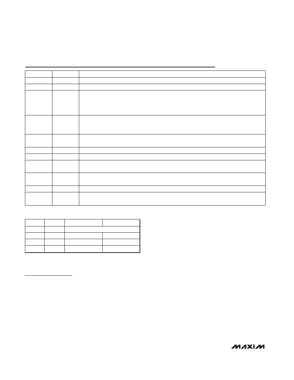
Pin Description
PIN
NAME
FUNCTION
1
IN
Supply Voltage Input. Connect to a 2.6V to 5.5V source.
2
GND
Ground. Connect to PGND.
3
SS
Soft-Start Control. Connect a 1000pF capacitor (C
SS
) from SS to GND to eliminate input-current
overshoot during startup. C
SS
is required for normal operation of the MAX1556/MAX1557. For greater
than 22µF total output capacitance, increase C
SS
to C
OUT
/ 22,000 for soft-start. SS is internally
discharged through 200
Ω to GND in shutdown.
4
OUT
Output Sense Input. Connect to the output of the regulator. D1 and D2 select the desired output
voltage through an internal feedback resistor-divider. The internal feedback resistor-divider remains
connected in shutdown.
5
SHDN
Shutdown Input. Drive SHDN low to enable low-power shutdown mode. Drive high or connect to IN
for normal operation.
6
D2
OUT Voltage-Select Input. See Table 1.
7
PGND
Power Ground. Connect to GND.
8
LX
Inductor Connection. Connected to the drains of the internal power MOSFETs. High impedance in
shutdown mode.
9
INP
Supply Voltage, High-Current Input. Connect to a 2.6V to 5.5V source. Bypass with a 10µF ceramic
capacitor to PGND.
10
D1
OUT Voltage-Select Input. See Table 1.
EP
—
Exposed Paddle. Connect to ground plane. EP also functions as a heatsink. Solder to circuit-board
ground plane to maximize thermal dissipation.
D1
D2
MAX1556 V
OUT
MAX1557 V
OUT
0
0
Adjustable from 0.75V to V
IN
0
1
3.3V
1.5V
1
0
2.5V
1.3V
1
1
1.8V
1.0V
Table 1. Output-Voltage-Select Truth Table
A zero represents D_ being driven low or connected to GND.
A 1 represents D_ being driven high or connected to IN.