16µa i, 2a pwm dc-dc step-down converters, Chip information – Rainbow Electronics MAX1557 User Manual
Page 10
MAX1556/MAX1557
Inductor Selection
A 4.7µH inductor with a saturation current of at least
800mA is recommended for the MAX1557 full-load
(600mA) application. For the MAX1556 application with
1.2A full load, use a 3.3µH inductor with at least 1.34A
saturation current. For lower full-load currents the
inductor current rating can be reduced. For maximum
efficiency, the inductor’s resistance (DCR) should be as
low as possible. Please note that the core material dif-
fers among different manufacturers and inductor types
and has an impact on the efficiency. See Table 2 for
recommended inductors and manufacturers.
Capacitor Selection
Ceramic input and output capacitors are recommend-
ed for most applications. For best stability over a wide
temperature range, use capacitors with an X5R or bet-
ter dielectric due to their small size, low ESR, and low
temperature coefficients.
Output Capacitor
The output capacitor C
OUT
is required to keep the out-
put voltage ripple small and to ensure regulation loop
stability. C
OUT
must have low impedance at the switch-
ing frequency. A 22µF ceramic output capacitor is rec-
ommended for most applications. If a larger output
capacitor is used, then paralleling smaller capacitors is
suggested to keep the effective impedance of the
capacitor low at the switching frequency.
Input Capacitor
Due to the pulsating nature of the input current in a buck
converter, a low-ESR input capacitor at INP is required
for input voltage filtering and to minimize interference
with other circuits. The impedance of the input capacitor
C
INP
should be kept very low at the switching frequen-
cy. A minimum value of 10µF is recommended at INP for
most applications. The input capacitor can be increased
for better input filtering.
IN Input Filter
In all MAX1557 applications, connect INP directly to IN
and bypass INP as described in the Input Capacitor sec-
tion. No additional bypass capacitor is required at IN.
For applications using the MAX1556, an RC filter
between INP and IN keeps power-supply noise from
entering the IC. Connect a 100
Ω resistor between INP
and IN, and connect a 0.47µF capacitor from IN to GND.
Soft-Start Capacitor
The soft-start capacitor, C
SS
, is required for proper
operation of the MAX1556/MAX1557. The recommend-
ed value of C
SS
is discussed in the Soft-Start section.
Soft-start times for various soft-start capacitors are
shown in the Typical Operating Characteristics.
PC Board Layout and Routing
Due to fast-switching waveforms and high-current
paths, careful PC board layout is required. An evalua-
tion kit (MAX1556EVKIT) is available to speed design.
When laying out a board, minimize trace lengths
between the IC, the inductor, the input capacitor, and
the output capacitor. Keep these traces short, direct,
and wide. Keep noisy traces, such as the LX node
trace, away from OUT. The input bypass capacitors
should be placed as close to the IC as possible.
Connect GND to the exposed paddle and star PGND
and GND together at the output capacitor. The ground
connections of the input and output capacitors should
be as close together as possible.
Chip Information
TRANSISTOR COUNT: 7567
PROCESS: BiCMOS
16µA I
Q
, 1.2A PWM DC-DC
Step-Down Converters
10
______________________________________________________________________________________
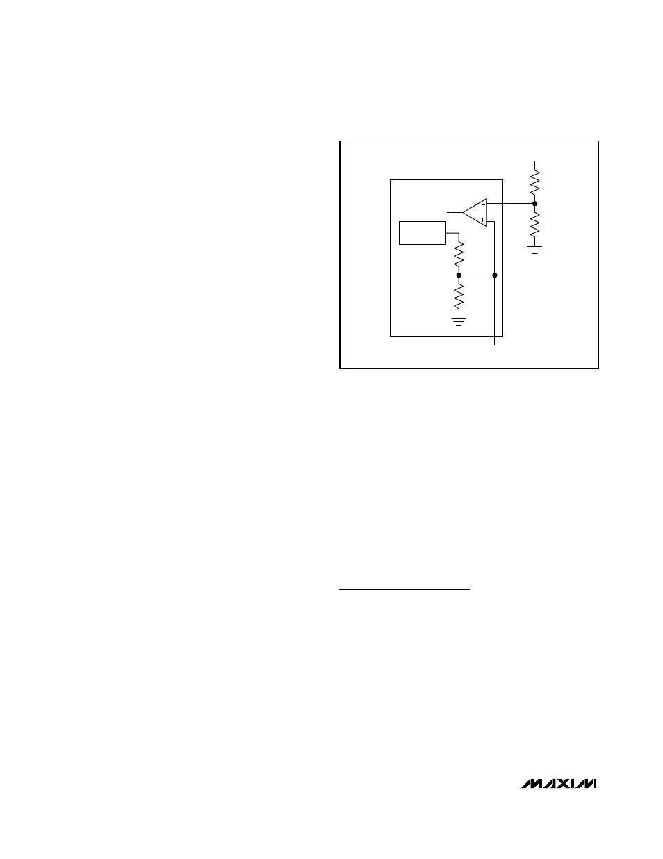
OUTPUT
OUT
R2
R3
SS
REFERENCE
1.25V
ERROR
AMPLIFIER
Figure 6. Adjustable Output Voltage