Rainbow Electronics MAX685 User Manual
Page 9
Setting the Output Voltage
The resistor-divider formed by R4 and R3 sets the neg-
ative output voltage; the resistor-divider formed by R1
and R2 sets the positive output voltage. Let R4 be a
value near 100k
Ω
to set a resistor-divider current of
approximately 10µA. Determine the value of R3 by the
following:
Let R2 be a value near 100k
Ω
to set a resistor-divider
current of approximately 10µA. Determine the value of
R1 with the following formula:
R1 = R2 x (V
OUT
+ - 1.24V) / 1.24
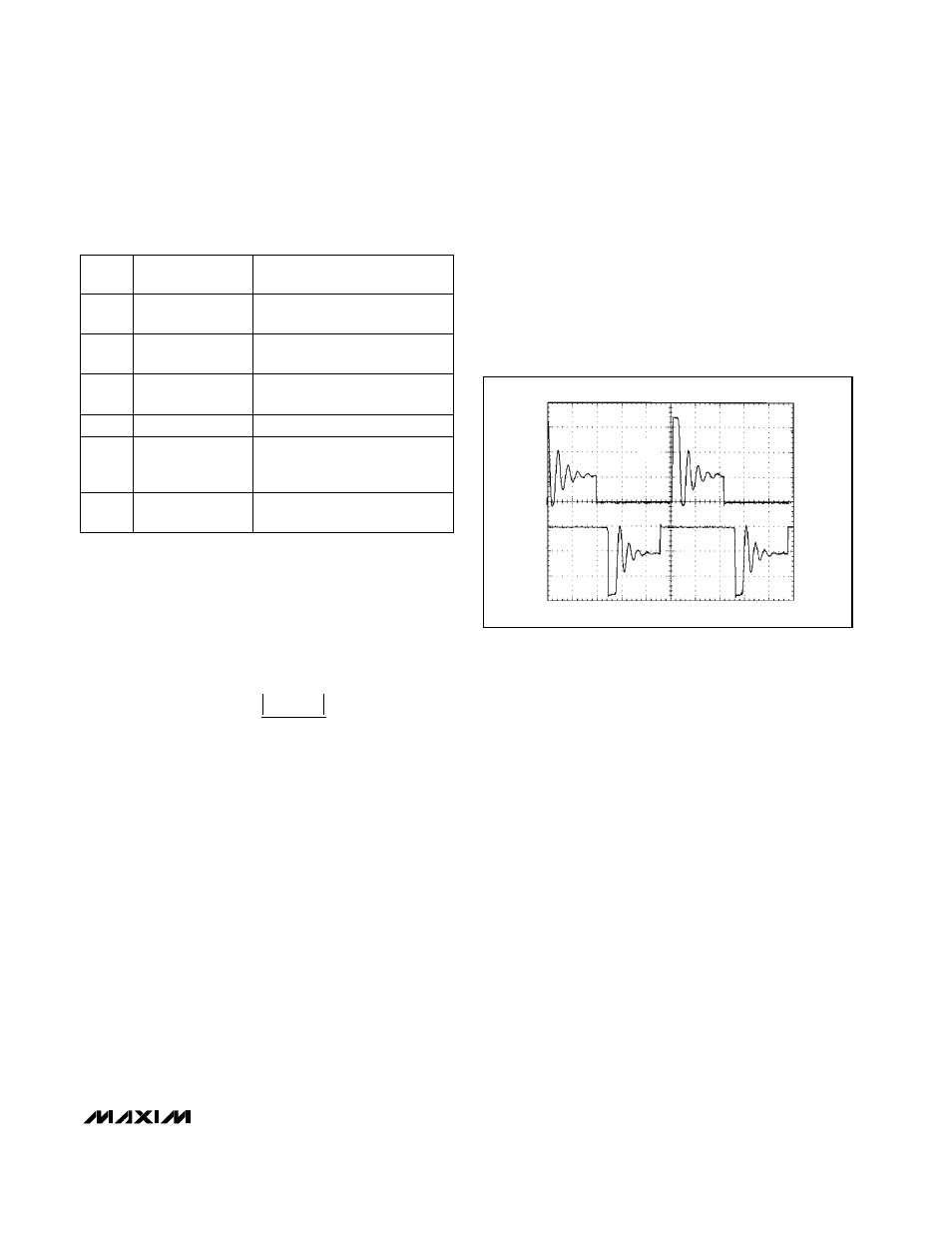
Damping LX
LXN and LXP may ring at the conclusion of each
switching cycle when the inductor current falls to zero.
Typically the ringing waveform appears only on LX_
and has no effect on output ripple and noise. If LX_
ringing is still objectionable, it may be damped by con-
necting a series RC in parallel with L1. Typically 1k
Ω
in
series with 100pF provides good damping with only 3%
efficiency degradation. See Figure 5.
R
R
V
V
OUT
3
4
1 24
.
=
−
MAX685
Dual-Output (Positive and Negative),
DC-DC Converter for CCD and LCD
_______________________________________________________________________________________
9
Any manufacturer
0.22µF ceramic
capacitor
C2
Any manufacturer
47pF ceramic cap
C5
Any manufacturer
2.2µF ceramic
capacitor
C3, C4
Murata LHQ4N220J04 or
TDK NLC32522T-220K
22µH, 0.4A
inductor
L1
Motorola MBR0520LT1 (0.5A)
or Central Semiconductor
CMPSH-3
0.1A, 20V
Schottky rectifier
D1, D2
REF
Sprague 595D106X0010A2T or
AVX TAJA106K010R
10µF, 10V
tantalum cap
C1
MANUFACTURER
PART NUMBER
DESCRIPTION
Table 1. Component Values for the
Typical Operating Circuit
Figure 5. LXN and LXP Waveforms with a Series-Connected
1k
Ω
Resistor and 100pF Capacitor Connected in Parallel with
L1 to Damp Ringing
+15V
+5V
0V
+5V
0V
-7.5V
LXN
LXP