Max685, Applications information, Higher output voltages – Rainbow Electronics MAX685 User Manual
Page 8: Inductor selection, Filter capacitor selection
MAX685
Applications Information
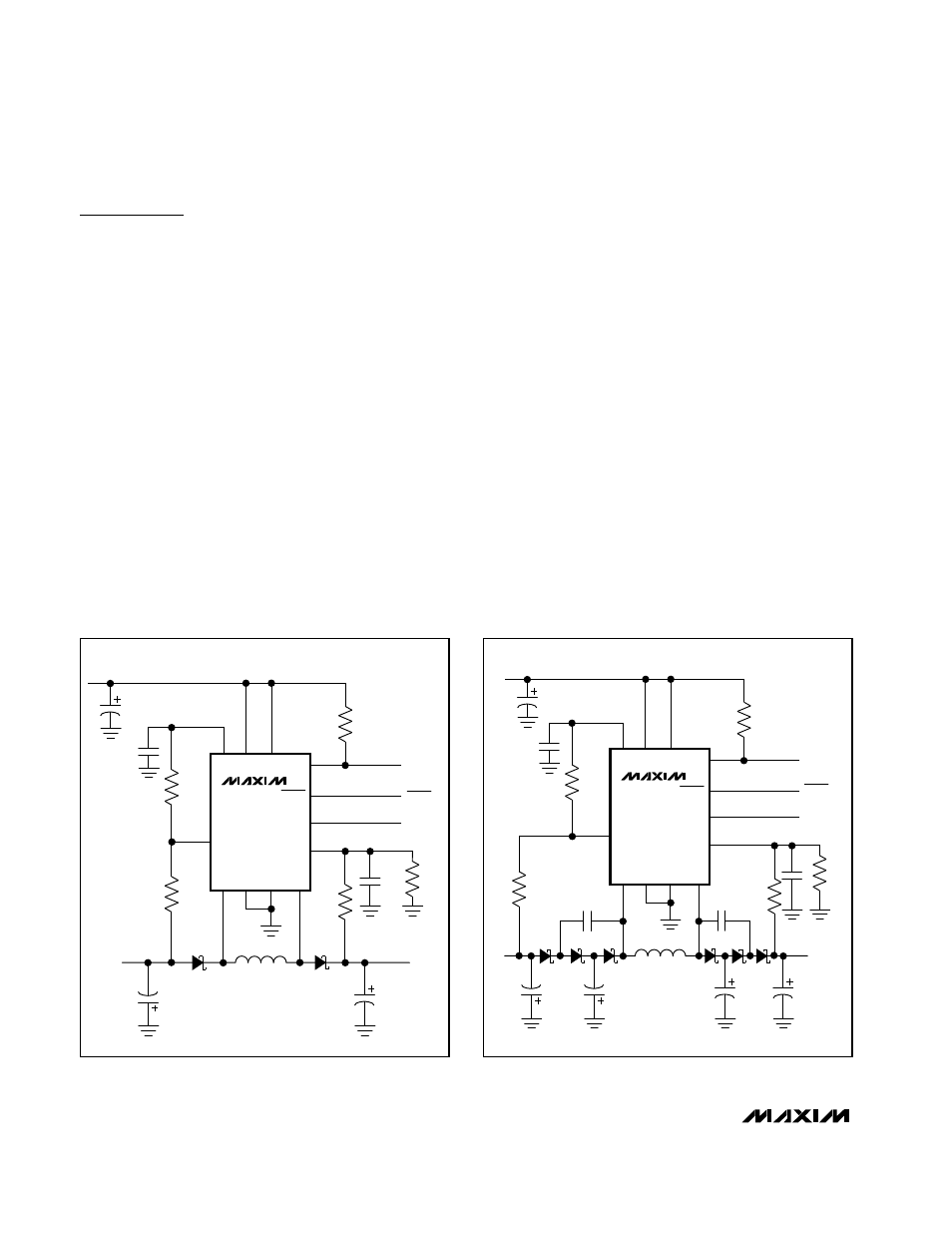
Figure 3 shows the standard application circuit for the
MAX685. The values shown in Table 1 will work well for
output currents up to 10mA. However, this circuit can
be optimized to a particular application by using differ-
ent capacitors and a different inductor.
Higher Output Voltages
If the application requires output voltages greater than
-7.5V or +24V, use the circuit of Figure 4. This circuit
uses a charge pump to increase the output voltage
without increasing the voltage stress on the LX_ pin.
The maximum output voltages of the circuit in Figure 4
are -15V and +48V.
The voltage rating on D2, D5, and D6 must be 30V or
greater. For a larger negative output voltage without a
larger positive output (or vice versa), use one-half of
the Figure 4 circuit with one-half of the Figure 3 circuit.
Inductor Selection
A 22µH inductor is suitable for most applications.
Larger inductances will reduce inductor ripple current
and output voltage ripple, but they also typically require
larger physical size if increased resistance and losses
are not also allowed.
Small inductors are typically preferred because of
compact design and low cost. Murata LHQ and
TDK NLC types are examples of small surface-mount
inductors that work for most applications. Because these
small-size inductors use thinner wire, they exhibit higher
resistance and have greater losses than larger ones. If
the application demands higher efficiency, use larger,
lower resistance coils such as the Sumida CD43 or CD54,
Coilcraft DT1608 or DO1608, or Coiltronics UP1V series.
Filter Capacitor Selection
The output ripple voltage is a function of the peak in-
ductor current, frequency, and type and value of the
output capacitors. Capacitors with low equivalent-
series resistance (ESR) and large capacitance reduce
output ripple. Typically, tantalum or ceramic capacitors
are optimal. Tantalum capacitors have higher ESR and
higher capacitance than ceramic capacitors. Therefore
the ESR of tantalum capacitors determines the output
ripple, because at the frequencies used the ESR domi-
nates the impedance of the capacitor. If ceramic
capacitors are used, the capacitance determines the
output ripple.
Dual-Output (Positive and Negative),
DC-DC Converter for CCD and LCD
8
_______________________________________________________________________________________
MAX685
REF VP
V
DD
LXP
1
11
3
8
9
13, 14 16
FBN
10
POK
4
6
7
12
POK
SHDN
SYNC
C5
47pF
R1
1.0M
R5
100k
D2
NBR0520
L1
22
µ
H
D1
NBR0520
R2
90.9k
+15V
V
OUT+
C4
2.2
µ
F
C3
2.2
µ
F
C2
0.22
µ
F
C1
10
µ
F
V
IN
R3
750k
R4
124k
-7.5V
V
OUT-
SHDN
PGND LXN
GND
SYNC
FBP
Figure 3. Standard Application Circuit
MAX685
REF VP
V
DD
LXP
C6
1
µ
F
1
11
3
8
9
13, 14 16 C8
1
µ
F
FBN
10
POK
4
6
7
12
POK
SHDN
SYNC
C5
47pF
R1
R5
100k
D2
D5
D6
L1
22
µ
H
D3
D4
D1
R2
V
OUT+
C9
2.2
µ
F
C7
2.2
µ
F
C3
2.2
µ
F
C2
0.22
µ
F
C1
10
µ
F
V
IN
R3
R4
V
OUT-
SHDN
PGND LXN
GND
SYNC
FBP
C4
2.2
µ
F
Figure 4. Circuit for Output Voltages < -9V and > +24V