Note 4), Note 5), Note 6) – Rainbow Electronics LM41 User Manual
Page 7: Note 7), Note 8), Note 9), Note 12), Note 10), Error(note 11), Note 13)
PIN
#
Pin
Name
Pin
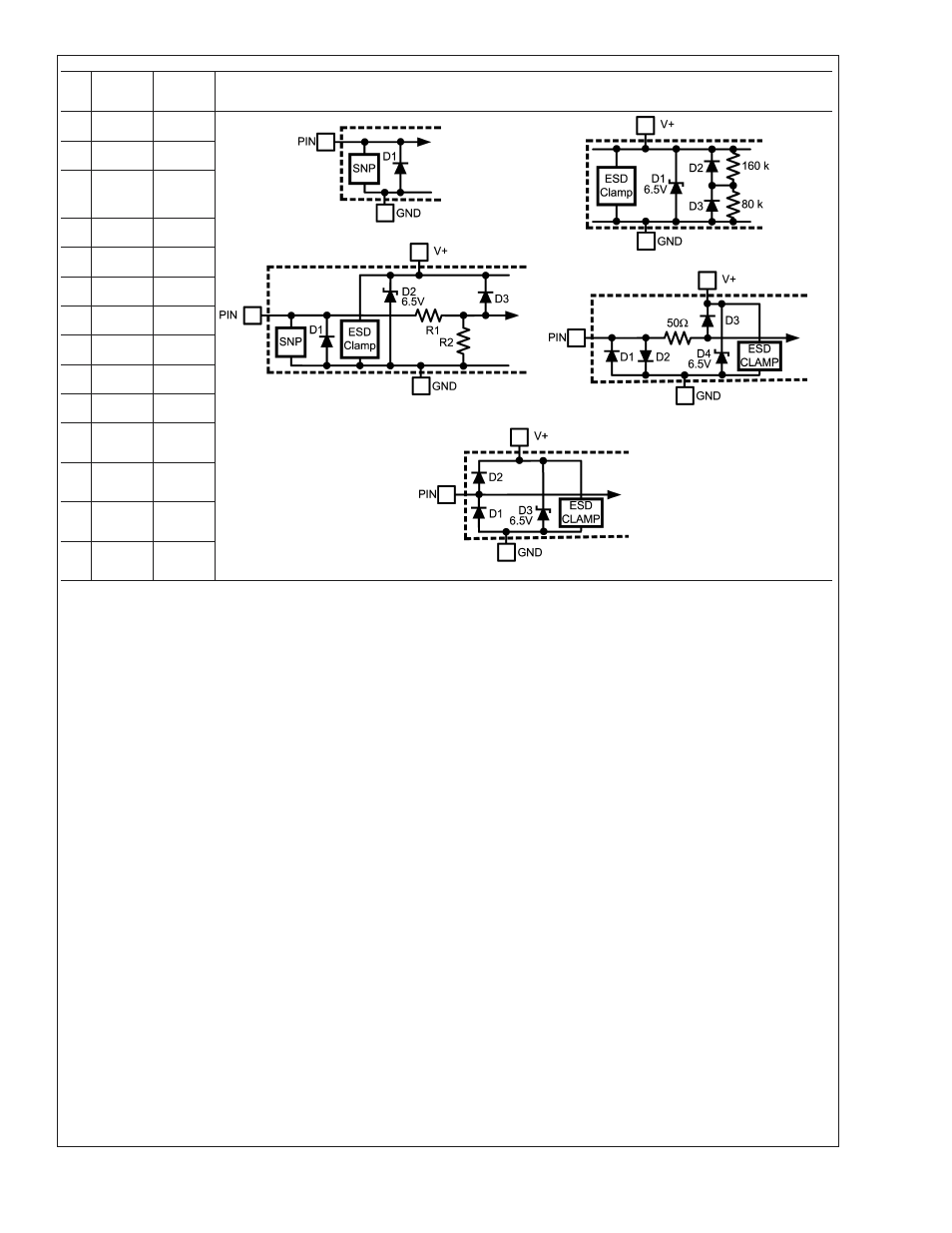
Circuit
All Input Structure Circuits
1
NC
A
Circuit A
Circuit C
Circuit B
Circuit D
2
GND
B
3
V+/
3.3V SB
B
4
SWD
A
5
ADD
A
6
+1.2V
C
7
+2.5V
C
8
D-
D
9
D+
E
10
NC
E
11
+5V
C
Circuit E
12
+12V
C
13
NC
none
14
NC
A
Note 4: Thermal resistance junction-to-ambient in still air when attached to a printed circuit board with 1 oz. foil is 148 ˚C/W.
Note 5: Human body model, 100 pF discharged through a 1.5 k
Ω resistor. Machine model, 200 pF discharged directly into each pin.
Note 6: Reflow temperature profiles are different for lead-free and non lead-free packages.
Note 7: “Typicals” are at T
A
= 25˚C and represent most likely parametric norm. They are to be used as general reference values not for critical design calculations.
Note 8: Limits are guaranteed to National’s AOQL (Average Outgoing Quality Level).
Note 9: The supply current will not increase substantially with a SensorPath transaction.
Note 10: Local temperature accuracy does not include the effects of self-heating. The rise in temperature due to self-heating is the product of the internal power
dissipation of the LM41 and the thermal resistance. See (Note 4) for the thermal resistance to be used in the self-heating calculation.
Note 11: TUE , total unadjusted error, includes ADC gain, offset, linearity and reference errors. TUE is defined as the "actual Vin" to achieve a given code transition
minus the "theoretical Vin" for the same code. Therefore, a positive error indicates that the input voltage is greater than the theoretical input voltage for a given code.
If the theoretical input voltage was applied to an LM41 that has positive error, the LM41’s reading would be less than the theoretical.
Note 12: The accuracy of the LM41CIMT is guaranteed when using the thermal diode of an Intel 90 nm Pentium 4 processor or any thermal diode with a non-ideality
factor of 1.011 and series resistance of 3.33
Ω. When using a MMBT3904 type transistor as a thermal diode the error band will be typically shifted by -4.5 ˚C.
Note 13: This specification is provided only to indicate how often temperature and voltage data are updated.
Note 14: The output fall time is measured from (V
IH min
) to (V
IL max
).
Note 15: The output rise time is measured from (V
IL max
) to (V
IH min
).
Note 16: The rise and fall times are not tested but guaranteed by design.
LM41
www.national.com
7