Pin(note 3), Note 3), Ac electrical characteristics – Rainbow Electronics LM41 User Manual
Page 6: Lm41
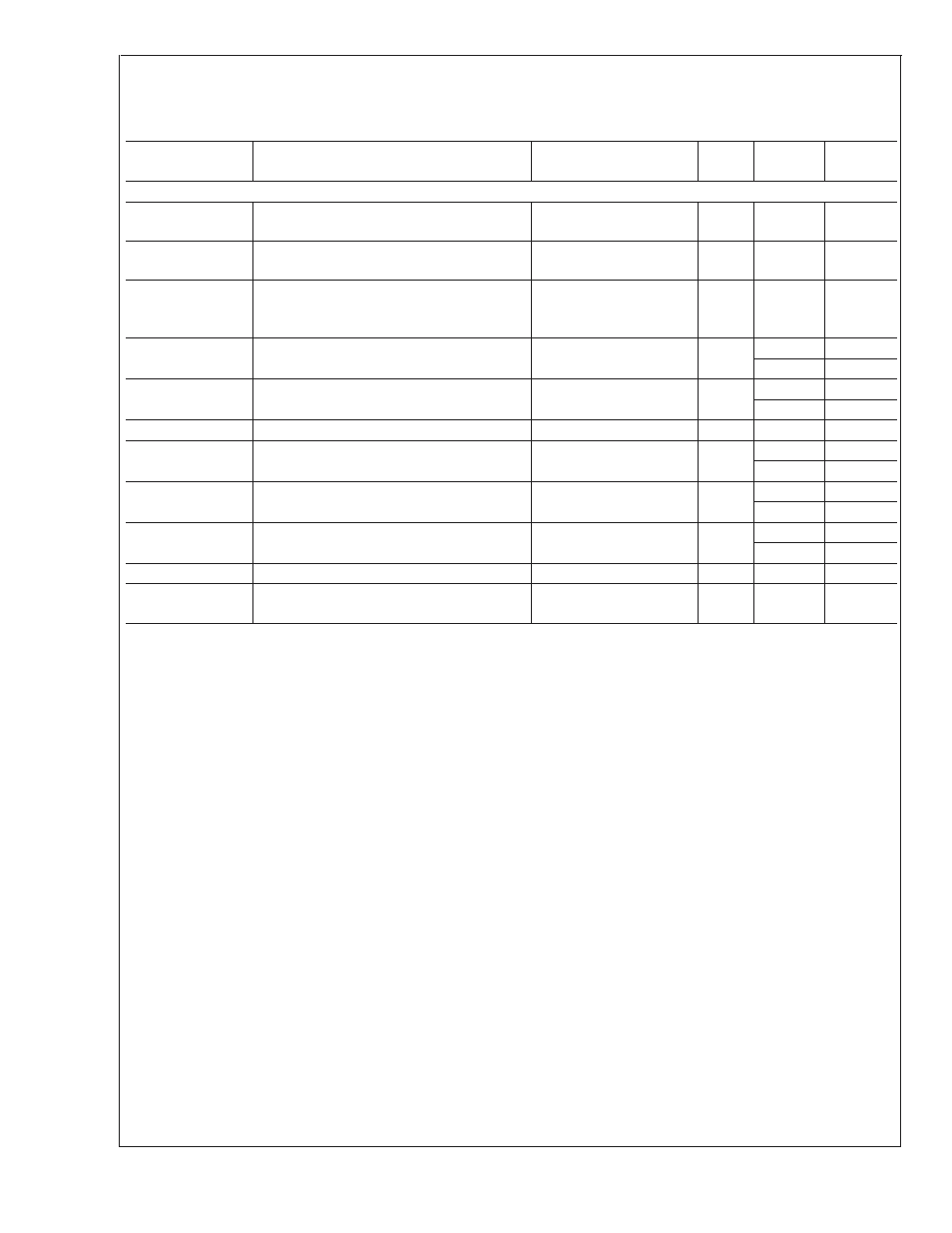
AC Electrical Characteristics
(Continued)
The following specification apply for V+ = +3.0 V
DC
to +3.6 V
DC
, unless otherwise specified. Boldface limits apply for
T
A
= T
J
= T
MIN
=0˚C to T
MAX
=85˚C; all other limits T
A
= T
J
= 25˚C. The SensorPath Characteristics conform to the SensorPath
specification revision 0.98. Please refer to that speciation for further details.
Symbol
Parameter
Conditions
Typical
Limits
Units
(Limits)
SensorPath Bus CHARACTERISTICS
t
f
SWD fall time (Note 16)
R
pull-up
=1.25 k
Ω
±
30%,
C
L
=400 pF
300
ns (max)
t
r
SWD rise time (Note 16)
R
pull-up
=1.25 k
Ω
±
30%,
C
L
=400 pF
1000
ns (max)
t
INACT
Minimum inactive time (bus at high level)
guaranteed by the slave before an attention
request
11
µs (min)
t
Mtr0
Master drive for Data Bit 0 write and for Data
Bit 0-1read
11.8
µs (min)
17.0
µs (max)
t
Mtr1
Master drive for Data Bit 1 write
35.4
µs (min)
48.9
µs (max)
t
SFEdet
Time allowed for LM41 activity detection
9.6
µs (max)
t
SLout1
LM41 drive for Data Bit 1 read by master
28.3
µs (min)
38.3
µs (max)
t
MtrS
Master drive for Start Bit
80
µs (min)
109
µs (max)
t
SLoutA
LM41 drive for Attention Request
165
µs (min)
228
µs (max)
t
RST
Master or LM41 drive for Reset
354
µs (min)
t
RST_MAX
Maximum drive of SWD by an LM41, after the
power supply is raised above 3V
500
ms (max)
Note 1: Absolute Maximum Ratings indicate limits beyond which damage to the device may occur. Operating Ratings indicate conditions for which the device is
functional, but do not guarantee performance limits. For guaranteed specifications and test conditions, see the Electrical Characteristics. The guaranteed
specifications apply only for the test conditions listed. Some performance characteristics may degrade when the device is not operated under the listed test
conditions.
Note 2: All voltages are measured with respect to GND, unless otherwise noted.
Note 3: When the input voltage (V
IN
) at any pin exceeds the power supplies (V
IN
<
GND or V
IN
>
V+), the current at that pin should be limited to 5 mA. Parasitic
components and/or ESD protection circuitry are shown below for the LM41’s pins. The nominal breakdown voltage of the zener is 6.5 V. SNP stands for snap-back
device.
LM41
www.national.com
6