Typical performance characteristics, Note 1), Note 2) – Rainbow Electronics LM3813 User Manual
Page 4: Note 3), Note 4), Note 5), Note 6), Note 7), Note 8), Electrical characteristics
Electrical Characteristics
(Continued)
Common Device Parameters
(Continued)
Unless otherwise specified, V
DD
= 5.0V for the following specifications. Supply bypass capacitor is 1 µF and filter capacitor is
0.1 µF.
Symbol
Parameter
Conditions
Typ
Limit
Units
V
OH
Logic High Level for PWM
Load current = 1 mA, 2V
≤ V
DD
≤
5.25V
V
DD
− 0.05
V
DD
− 0.2
V
V (min)
V
OL
Logic Low Level for PWM
Sink current = 1 mA, 2V
≤ V
DD
≤
5.25V
0.04
V
0.2
V (max)
P
I
Insertion Loss
I
SENSE
= 1A (Note 9)
0.004
Ω
Note 1: Absolute Maximum Ratings indicate limits beyond which damage to the device may occur. Operating Ratings indicate conditions for which the device is
intended to be functional, but do not guarantee specific performance limits. For guaranteed specifications and test conditions, see Electrical Characteristics. The
guaranteed specifications apply only for the test conditions listed. Some performance characteristics may degrade when the device is not operated under the listed
test conditions.
Note 2: At elevated temperatures, devices must be derated based on package thermal resistance. The device in the surface-mount package must be derated at
θ
JA
= 150˚C/W (typically), junction-to-ambient.
Note 3: The human body model is a 100 pF capacitor discharged through a 1.5 k
Ω resistor into each pin.
Note 4: The absolute maximum peak and continuous currents specified are not tested. These specifications are dependent on the
θ
JA
, which is 150˚C/W for the
S08 package.
Note 5: Typical numbers are at 25˚C and represent the most likely parametric norm. Specifications in standard type face are for T
J
= 25˚C and those with boldface
type apply over full operating temperature ranges.
Note 6: Limits are 100% production tested at 25˚C. Limits over the operating temperature range are guaranteed through correlation using Statistical Quality Control
(SQC) methods. The limits are used to calculate National’s Averaging Outgoing Quality Level (AOQL).
Note 7: There is a variation in accuracy over time due to thermal effects. Please refer to the “PWM Output and Current Accuracy” section for more information.
Note 8: The PWM accuracy for LM3812-7.0 and LM3813-7.0 depends on the amount of copper area under pins 1 and 2, and the layout. Please refer to the “PWM
Output and Current Accuracy” section for more information.
Note 9: The tolerance of the internal lead frame resistor is corrected internally. The temperature coefficient of this resistor is 2600 ppm/˚C.
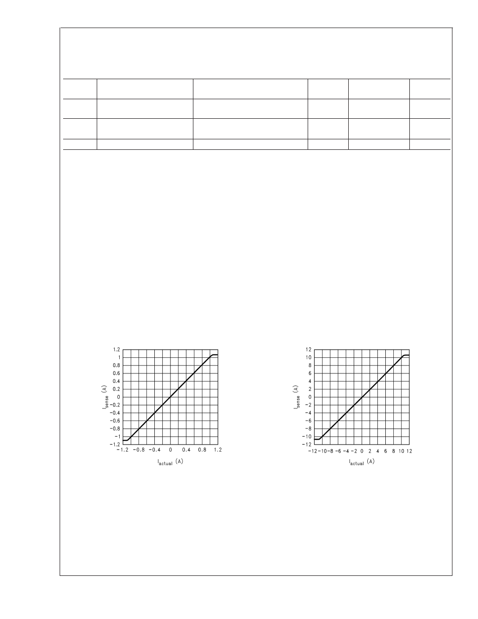
Typical Performance Characteristics
Supply bypass capacitor is 0.1 µF and filter capacitor is
0.1 µF.
Measured Current vs Actual Current
(LM3812-1.0 and LM3813-1.0)
Measured Current vs Actual Current
(LM3812-7.0 and LM3813-7.0)
10012215
10012224
LM3812/LM3813
www.national.com
4