2 power up and power down, 3 i2c bus interface, Figure 4. o.s. output temperature response diagram – Rainbow Electronics LM75 User Manual
Page 8: 0 functional description, Lm75
1.0 Functional Description
(Continued)
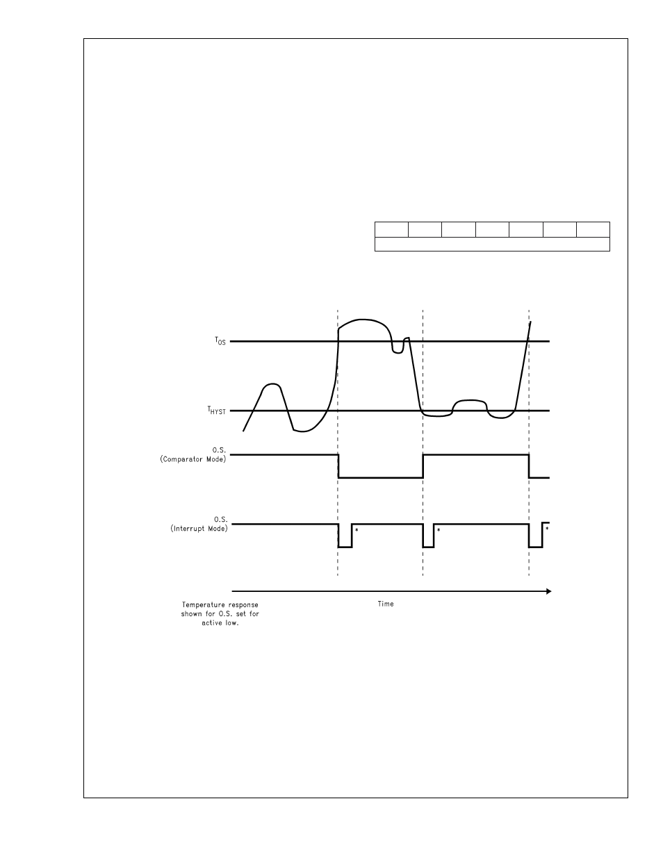
by crossing T
OS
, then reset, it can be activated again only by
Temperature going below T
HYST
. Again, it will remain active
indefinitely until being reset by a read. Placing the LM75 in
shutdown mode also resets the O.S. Output.
1.2 POWER UP AND POWER DOWN
The LM75 always powers up in a known state. The power up
default conditions are:
1.
Comparator mode
2.
T
OS
= 80˚C
3.
T
HYST
= 75˚C
4.
O.S. active low
5.
Pointer = “00”
If the LM75 is not connected to the I
2
C bus on power up, it
will act as a stand-alone thermostat with the above tempera-
ture settings.
When the supply voltage is less than about 1.7V, the LM75 is
considered powered down. As the supply voltage rises
above the nominal 1.7V power up threshold, the internal
registers are reset to the power up default values listed
above.
1.3 I
2
C BUS INTERFACE
The LM75 operates as a slave on the I
2
C bus, so the SCL
line is an input (no clock is generated by the LM75) and the
SDA line is a bi-directional serial data path. According to I
2
C
bus specifications, the LM75 has a 7-bit slave address. The
four most significant bits of the slave address are hard wired
inside the LM75 and are “1001”. The three least significant
bits of the address are assigned to pins A2–A0, and are set
by connecting these pins to ground for a low, (0); or to +V
S
for a high, (1).
Therefore, the complete slave address is:
1
0
0
1
A2
A1
A0
MSB
LSB
01265807
Note 14: These interrupt mode resets of O.S. occur only when LM75 is read or placed in shutdown. Otherwise, O.S. would remain active indefinitely for any event.
FIGURE 4. O.S. Output Temperature Response Diagram
LM75
www.national.com
8