Applications information, Starting a conversion, Sclk – Rainbow Electronics MAX1273 User Manual
Page 12: Power-on reset, Internal or external reference
MAX1272/MAX1273
Starting a Conversion
The MAX1272/MAX1273 use the serial clock to complete
an acquisition. The falling edge of CS does not start a
conversion on the MAX1272/MAX1273. Each conversion
requires a control byte. Programming the fourth bit in the
control byte starts the acquisition sequence. Conversion
starts on the falling edge of the eighth clock cycle after
the start bit.
Keep CS low during successive conversions. If a start bit
is received after CS transitions from high to low, but before
the output bit 4 (D4) becomes available, the current con-
version terminates and a new conversion begins. DOUT
enters high-impedance state when CS transitions high.
SCLK
shifts data in and out of the MAX1272/MAX1273
and controls both acquisition and conversion timing.
Conversion begins immediately after the end of the
acquisition cycle. Successive-approximation bit deci-
sions appear at DOUT on each of the following 12 clock
falling edges (Figure 5). Additional clock falling edges
result in trailing zeros at DOUT.
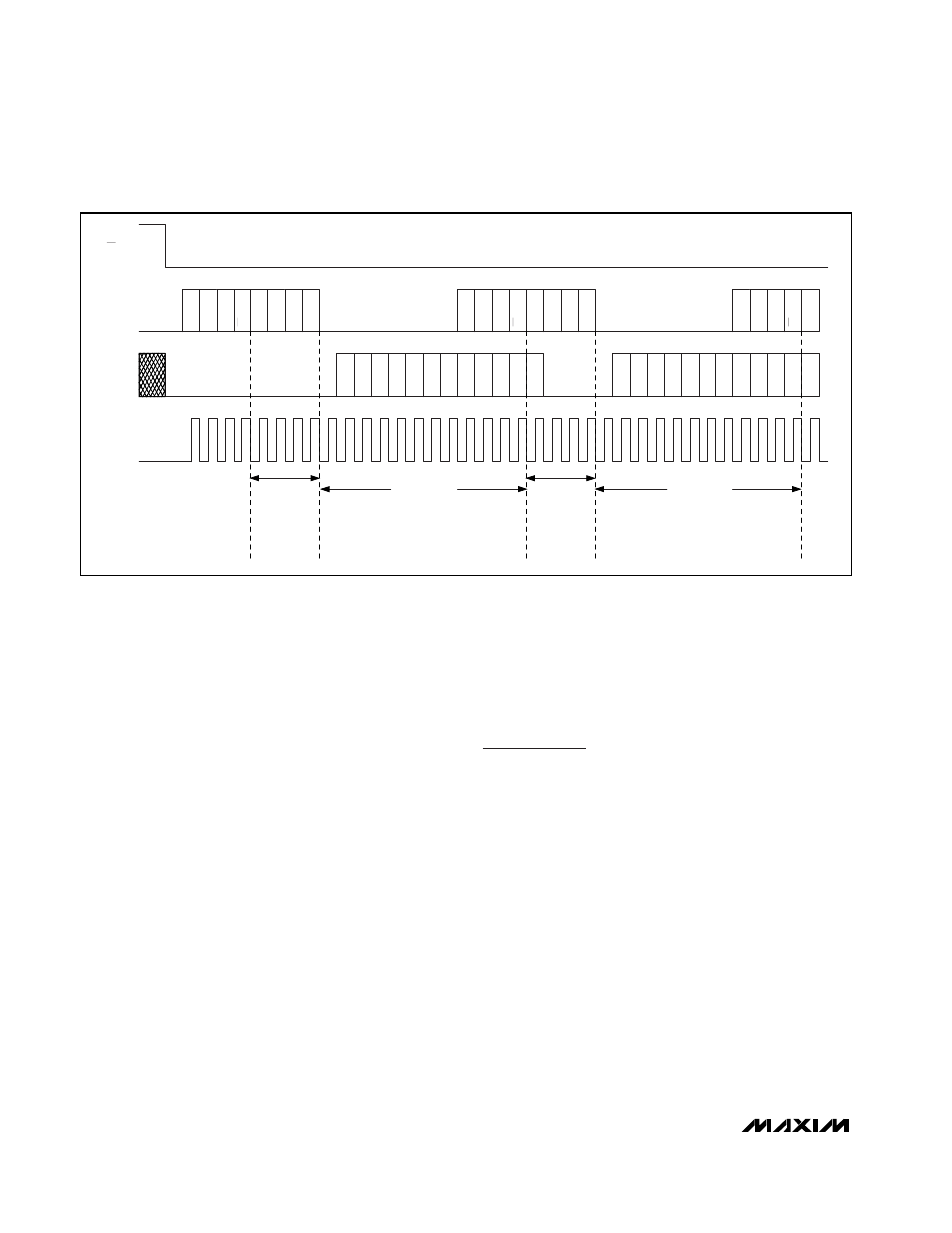
The maximum running rate of the MAX1272/MAX1273 is
16 clocks per conversion. A clock speed of 1.4MHz
allows for a maximum sampling rate of 87ksps (Figure 6).
To achieve the maximum throughput, keep CS low, and
start the control byte after bit 4 (D4) of the conversion in
progress clocks out on DOUT.
If CS is low and SCLK is continuous, guarantee a start
bit by first clocking in 16 zeros.
Applications Information
Power-On Reset
The MAX1272/MAX1273 power-up in normal operating
mode (all internal circuitry active), and external reference
mode. The MAX1272/MAX1273 require a start bit to initi-
ate a conversion. The contents of the output data register
clear during power-up.
Internal or External Reference
Operate the MAX1272/MAX1273 with an internal or an
external reference. Configure REF as an internal refer-
ence output or an external reference input using the
serial interface. When changing from external reference
mode to internal reference mode, allow 2ms (C
REF
=
1µF) for the reference to stabilize before taking any
measurement.
Internal Reference
The internally trimmed reference provides 4.096V at REF.
Bypass REF to GND with a 1.0µF capacitor (Figure 7a).
Fault-Protected, 12-Bit ADCs
with Software-Selectable Input Range
12
______________________________________________________________________________________
1
8
16
24
32
CS
DIN
DOUT
SCLK
ACQUISITION
4 SCLKs
ACQUISITION
4 SCLKs
HI-Z
ST
AR
T
RNG
BIP
MODE1
PD
MODE0
RESERVED
REF
ST
AR
T
RNG
BIP
MODE1
PD
MODE0
RESERVED
REF
D11
D10
D9
D8
D0
D1
D2
D3
D4
D5
D6
D7
MSB
LSB
D11
D10
D9
D8
D0
D1
D2
D3
D4
D5
D6
D7
MSB
LSB
ST
AR
T
RNG
BIP
MODE1
PD
CONVERSION
12 SCLKs
CONVERSION
12 SCLKs
CONTROL BYTE 0
CONTROL BYTE 1
CONTROL BYTE 2
RESULT 0
RESULT 1
Figure 6. Conversion Timing, 16 Clocks/Conversion