Max2406, Low-cost downconverter with low-noise amplifier, Applications information – Rainbow Electronics MAX2406 User Manual
Page 6: Lo inputs, If output port, Power-down control, Extended frequency range
MAX2406
LO Inputs
The LO and LO pins are internally terminated with 50
Ω
resistors. See the
Typical Operating Characteristics
for
a plot of LO Port Return Loss vs. Frequency. AC couple
the local-oscillator signal to these pins. If a single-
ended LO source is used, connect LO to ground.
IF Output Port
The receive mixer output appears on the differential IF
and IF pins. These open-collector outputs each require
an external inductor to V
CC
for DC biasing. This port
typically requires a matching network for coupling to an
external IF filter. For single-ended operation, connect
the unused side (typically IF) to V
CC
, and decouple it to
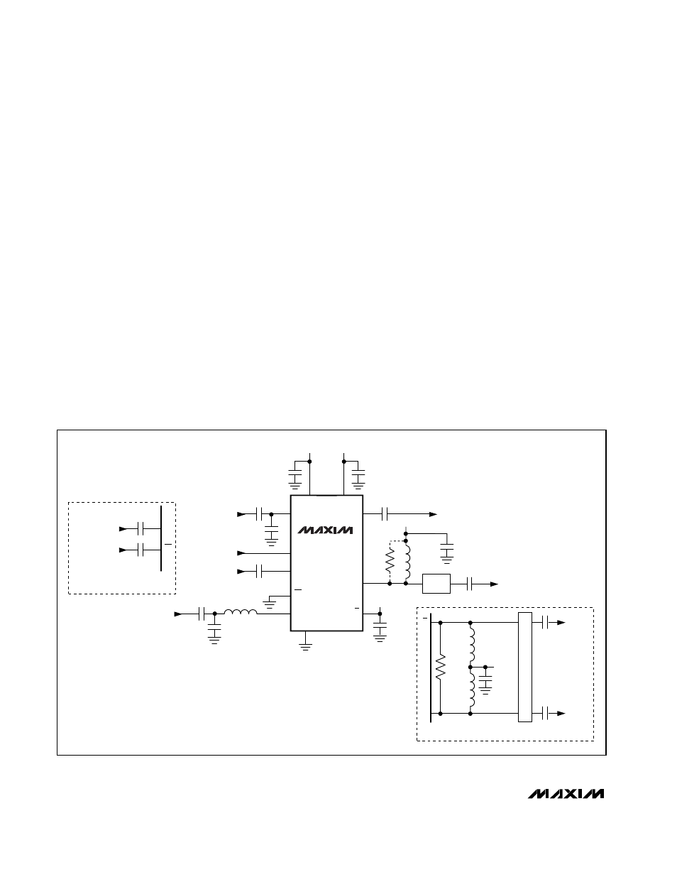
ground with a 1000pF capacitor. Figure 1 shows exam-
ples of single-ended and differential IF port connec-
tions. Refer to the IF and IF Output Impedance vs.
Frequency plot in the
Typical Operating Characteris-
tics
. At lower IF frequencies, a shunt resistor across the
pull-up inductor (in single-ended applications) or
across IF and IF (in differential applications) can be
used to set the IF impedance.
Power-Down Control
Pulling RXEN low places the MAX2406 in shutdown
mode. Power-down is guaranteed with a control voltage
at or below 0.6V. The device exits shutdown in 0.5µs
typical.
__________Applications Information
Extended Frequency Range
The MAX2406 has been characterized at 1.9GHz for
use in PCS applications; however, it operates over a
much wider frequency range. The LNA gain and noise
figure, as well as receive mixer conversion gain, are
plotted over a wide frequency range in the
Typical
Operating Characteristics
. When operating the device
at frequencies other than those specified in the specifi-
cation table, it may be necessary to design or alter the
matching networks on LNAIN, RXMIXIN, IF, and (if
used) IF. In some cases, the internal broadband output
match on LNAOUT may have to be supplemented by
an external matching circuit. The
Typical Operating
Characteristics
provide port-impedance data vs. fre-
quency for use in designing a matching network. The
Low-Cost Downconverter
with Low-Noise Amplifier
6
_______________________________________________________________________________________
Figure 1. MAX2406 Typical Operating Circuit
MAX2406
V
CC
V
CC
V
CC
V
CC
V
CC
V
CC
RXMXIN
IF
IF
LNAOUT
LNA OUTPUT
*OPTIONAL
IF OUTPUT
(SINGLE-ENDED)
IF OUTPUT
DIFFERENTIAL
DIFFERENTIAL IF OPERATION
GND
LO
LO
RXEN
LNAIN
LNA INPUT
RECEIVER
ENABLE
LO INPUT
(SINGLE-ENDED)
RECEIVE
MIXER
INPUT
47pF
47pF
2
9
5
19
13
L
CHOKE
L
CHOKE
L
CHOKE
14
14
13
1, 3, 4, 10,
11, 12, 15,
17, 18, 20
6
7
R*
R*
8
16
220pF
220pF
MATCH
220pF
LO
DIFFERENTIAL LO OPERATION
LO INPUT
DIFFERENTIAL
7
8
220pF
220pF
1000pF
V
CC
1000pF
1000pF
1000pF
1000pF
1000pF
4.7nH
*1pF
220pF
1pF
IF
IF
LO
MATCH