Design information – Rainbow Electronics MAX1643 User Manual
Page 8
MAX1642/MAX1643
High-Efficiency, Step-Up
DC-DC Converters for 1V Inputs
8
_______________________________________________________________________________________
BATTLO (MAX1643)
The MAX1643 contains an on-chip comparator for low-
battery detection. If the voltage at BATT drops below
1V, BATTLO sinks current. BATTLO is an open-drain
output. In combination with PFI/PFO, this allows moni-
toring of both the input and output voltages.
Reverse-Battery Protection
The MAX1642/MAX1643 can sustain/survive single-cell
battery reversal up to the package power-dissipation
limit. An internal 5
Ω
resistor in series with a diode limits
reverse current to less than 220mA, which prevents dam-
age to the MAX1642/MAX1643. Prolonged operation
above 220mA reverse-battery current can degrade the
devices’ performance.
________________Design Information
Output Voltage Selection
The MAX1642/MAX1643 operate with a 3.3V ±4% or
adjustable output. To select fixed-voltage operation, con-
nect FB to GND. For an adjustable output between 2V
and 5.2V, connect FB to a resistor voltage divider
between OUT and GND (Figure 4). FB regulates to 1.23V.
Since FB leakage is 10nA max, select feedback resistor
R2 in the 100k
Ω
to 1M
Ω
range. R1 is given by:
where V
REF
= 1.23V.
Power-Fail Detection
The MAX1642/MAX1643 have an on-chip comparator for
power-fail detection. This comparator can detect loss of
power at the input or output. If the voltage at PFI falls
below 614mV, the PFO output sinks current to GND.
Hysteresis at the power-fail input is 1%. The power-fail
monitor’s threshold is set by two resistors: R3 and R4
(Figure 5). Set the threshold using the following equation:
where V
TH
is the desired threshold of the power-fail
detector, and V
PFI
is the 614mV reference of the power-
fail comparator. Since PFI leakage is 10nA max, select
feedback resistor R4 in the 100k
Ω
to 1M
Ω
range.
Low-Battery Start-Up
The MAX1642/MAX1643 are bootstrapped circuits with
a low-voltage start-up oscillator. They can start under
low-load conditions at lower battery voltages than at full
load. Once started, the output can maintain the load as
the battery voltage decreases below the start-up volt-
age (see
Typical Operating Characteristics
).
Inductor Selection
A 100µH inductor is recommended for most appli-
cations. The use of lower inductor values (down to
68µH) increases maximum output current. Higher val-
ues (up to 220µH) reduce peak inductor current and
consequent ripple and noise. The inductor’s saturation-
current rating must exceed the peak current limit syn-
thesized by the MAX1642/MAX1643’s timing
algorithms:
where K
MAX
= 35V-µs. The maximum recommended
I
PEAK
is 350mA. For best efficiency, inductor series
resistance should be less than 1
Ω
.
I
=
K
L
PEAK
MAX
MIN
R3 = R4
V
V
- 1
TH
PFI
R1 = R2
V
V
- 1
OUT
REF
MAX1642
GND
FB
BATT
PFI
3.3V
OUT
0.88V to 1.65V INPUT
100
µ
H, 350mA
PF0
22
µ
F
0.1
µ
F
SHDN
LX
OUT
OUT
22
µ
F
0.1
µ
F
MAX1643
GND
FB
BATT
3.3V
OUT
0.88V to 1.65V INPUT
BATTLO
22
µ
F
0.1
µ
F
LX
OUT
PFI
PFO
22
µ
F
0.1
µ
F
OUT
100
µ
H, 350mA
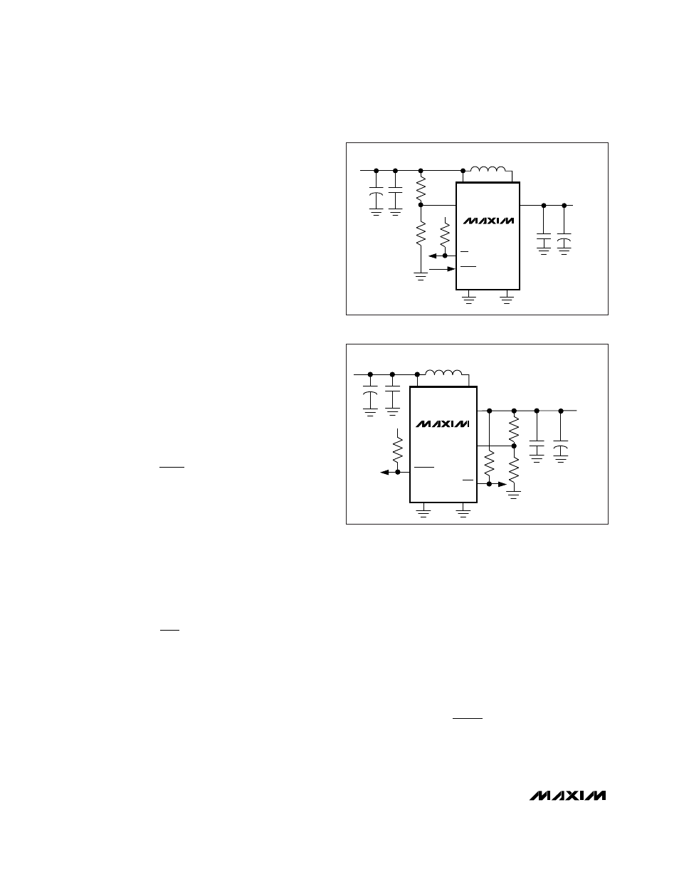
Figure 2. MAX1642 3.3V Standard Application Circuit
Figure 3. MAX1643 3.3V Standard Application Circuit