Rainbow Electronics MAX1643 User Manual
Page 6
MAX1642/MAX1643
High-Efficiency, Step-Up
DC-DC Converters for 1V Inputs
6
_______________________________________________________________________________________
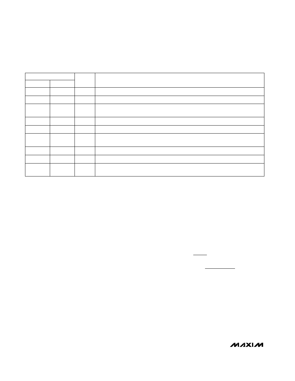
______________________________________________________________Pin Description
_______________Detailed Description
The MAX1642/MAX1643 each consist of an internal 1
Ω
,
N-channel MOSFET power switch, a built-in synchro-
nous rectifier that acts as the catch diode, an oscillator,
a reference, and PFM control circuitry (Figure 1).
These devices are optimized for applications with
power-management features that operate from one
alkaline cell, such as pagers, remote controls, and bat-
tery-powered instruments. They are designed to meet
the specific demands of the operating states character-
istic of such systems:
1)
Primary battery is good and the load is active:
In
this state, the system draws tens of milliamperes,
and the MAX1642/MAX1643 typically offer 80% effi-
ciency.
2)
Primary battery is good and the load is sleeping:
In
this state, the load is drawing hundreds of microam-
peres, and the DC-DC converter IC draws very low
quiescent current. In many applications, the load is
expected to be in this state most of the time.
Operating Principle
The MAX1642/MAX1643 employ a proprietary pulse-
frequency-modulation (PFM) control scheme that com-
bines the ultra-low quiescent current traditional of
pulse-skipping PFM converters with the high-load effi-
ciency of pulse-width-modulation (PWM) converters.
The on-time and minimum off-times are varied as a
function of the input and output voltages:
where K is typically 25V-µs. This enables the
MAX1642/MAX1643 to maintain high efficiency over a
wide range of loads and input/output voltages. The DC-
DC converter is powered from the OUT pin.
t
=
K
V
t
=
1.2 x K
V
- V
ON
BATT
OFF(MIN)
OUT
BATT
6
7
8
4
—
5
2
1
MAX1643
Ground
GND
6
N-Channel MOSFET Switch Drain and P-Channel Synchronous-Rectifier Drain
LX
7
Power Output. Feedback input for fixed 3.3V operation and IC power input. Connect filter
capacitor close to OUT.
OUT
8
Open-Drain Power-Fail Output. Sinks current when PFI drops below 614mV.
PFO
3
Active-Low Shutdown Input. Connect to BATT for normal operation.
SHDN
4
Feedback Input for adjustable-output operation. Connect FB to an external resistor voltage
divider between OUT and GND. Connect to GND for fixed-output operation.
FB
5
Power-Fail Input. When the voltage on PFI drops below 614mV, PFO sinks current.
PFI
2
IC Battery-Power Input. Sense input for BATTLO comparator (MAX1643 only).
BATT
1
PIN
3
Open-Drain Battery-Low Output. When the voltage at BATT drops below 1V, BATTLO
sinks current.
BATTLO
—
MAX1642
FUNCTION
NAME