Design procedure – Rainbow Electronics MAX1817 User Manual
Page 9
Low-Voltage Startup
The MAX1817’s internal circuitry is powered from OUT.
The main step-up converter has a low-voltage startup
circuit to control main DC-DC converter operation until
V
OUT
exceeds the 2.2V (typ) undervoltage lockout
threshold. The minimum startup voltage is a function of
load current (see Typical Operating Characteristics).
The MAX1817 main converter typically starts up into a
35
Ω load with input voltages down to +1.5V, allowing
startup with two alkaline cells even in deep discharge.
Shutdown: ON and ONLCD
The MAX1817 features independent shutdown control
of the main and LCD step-up converters. With both
converters shut down, supply current is reduced to
0.1µA. A logic low at ON shuts down the main step-up
converter, and LX enters a high-impedance state.
However, the main output remains connected to the
input through the inductor and output rectifier, holding
V
OUT
to one diode drop below the input voltage when
the main converter is shut down. If the input voltage is
sufficiently high to drive V
OUT
above the undervoltage
lockout voltage, the LCD step-up converter operates.
A logic low at ONLCD shuts down the LCD step-up
converter, and LXLCD enters a high-impedance state.
The LCD output remains connected to the input
through the inductor and output rectifier, holding it to
one diode drop below the input.
___________________Design Procedure
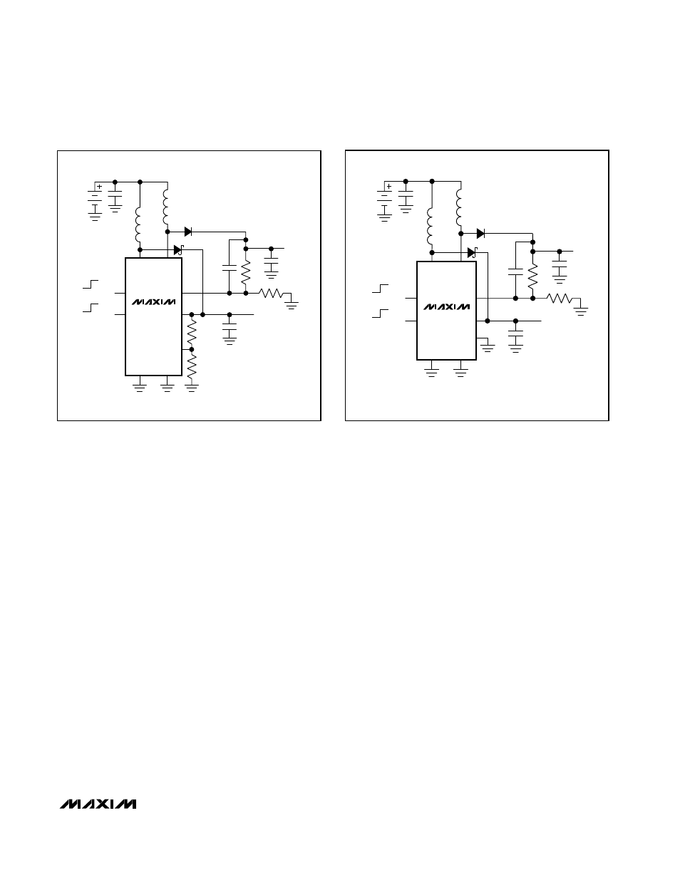
Setting the Main Output Voltage
The main step-up converter feedback input (FB) fea-
tures Dual Mode operation. With FB grounded, the
main output voltage is preset to 3.3V. It can also be
adjusted from 2.5V to 5.5V with external resistors R3
and R4 as shown in Figure 2. To set the output voltage
externally, select resistor R4 from 10k
Ω to 100kΩ.
Calculate R3 using:
R3 = R4 [(V
OUT
/ V
FB
) – 1]
where V
FB
= 1.25V, and V
OUT
can range from 2.5V to
5.5V.
Setting the LCD Output Voltage
Set the LCD output voltage with two external resistors
R1 and R2 as shown in Figure 3. Since the input leak-
age current at FBLCD has a maximum of 50nA, large
resistors can be used without significant accuracy loss.
Begin by selecting R2 in the 10k
Ω to 100kΩ range, and
calculate R1 using the following equation:
R1 = R2 [(V
LCD
/ V
FBLCD
) – 1]
where V
FBLCD
= 1.25V, and V
LCD
can range from V
IN
to 28V.
MAX1817
Compact, High-Efficiency, Dual-Output
Step-Up DC-DC Converter
_______________________________________________________________________________________
9
MAX1817
LX
ONLCD
ON
OFF
ON
FB
OUT
FBLCD
LCD
V
IN
MAIN 5V
LCD
R2 75k
R1
1M
R3
300k
R4
100k
D1
D2
C1
10
µF
L2
10
µH
L1
10
µH
4.7pF
C4
C2
1
µF
C3
22
µF
AGND
GND
LXLCD
OFF
ON
MAIN
18V
MAX1817
LX
ONLCD
ON
OFF
ON
FB
OUT
FBLCD
LCD
V
IN
MAIN 3.3V
LCD 18V
R2 75k
R1
1M
D1
D2
C1
10
µF
L2
10
µH
L1
10
µH
4.7pF
C4
C2
1
µF
C3
22
µF
AGND
GND
LXLCD
OFF
ON
MAIN
Figure 2. Setting Main Output Voltage Using External Resistors
Figure 3. Typical Application Circuit