Common device parameters, Lm3824 – Rainbow Electronics LM3824 User Manual
Page 4
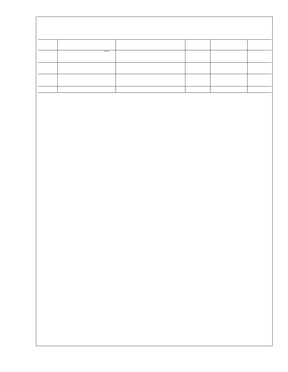
Common Device Parameters
(Continued)
Unless otherwise specified, V
DD
= 3.6V for the following specifications. Supply bypass capacitor is 1 µF and filter capacitor is
0.1 µF.
Symbol
Parameter
Conditions
Typ
(Note 5)
Limit
(Note 6)
Units
V
TL
Threshold Low Level for SD
1.2
V
0.7
V (max)
V
OH
Logic High Level for PWM
Load current = 1 mA, 2V
≤
V
DD
≤
5.25V
V
DD
− 0.05
V
DD
− 0.2
V
V (min)
V
OL
Logic Low Level for PWM
Sink current = 1 mA, 2V
≤
V
DD
≤
5.25V
0.04
V
0.2
V (max)
P
I
Insertion Loss
I
SENSE
= 1A (Note 9)
0.003
Ω
Note 1: Absolute Maximum Ratings indicate limits beyond which damage to the device may occur. Operating Ratings indicate conditions for which the device is in-
tended to be functional, but do not guarantee specific performance limits. For guaranteed specifications and test conditions, see Electrical Characteristics. The guar-
anteed specifications apply only for the test conditions listed. Some performance characteristics may degrade when the device is not operated under the listed test
conditions.
Note 2: At elevated temperatures, devices must be derated based on package thermal resistance. The device in the surface-mount package must be derated at
θ
JA
= 220˚C/W (typically), junction-to-ambient.
Note 3: The human body model is a 100 pF capacitor discharged through a 1.5 k
Ω
resistor into each pin.
Note 4: The absolute maximum peak and continuous currents specified are not tested. These specifications are dependent on the
θ
JA
, which is 220˚C/W for the
MSOP-8 package.
Note 5: Typical numbers are at 25˚C and represent the most likely parametric norm. Specifications in standard type face are for T
J
= 25˚C and those with boldface
type apply over full operating temperature ranges.
Note 6: Limits are 100% production tested at 25˚C. Limits over the operating temperature range are guaranteed through correlation using Statistical Quality Control
(SQC) methods. The limits are used to calculate National’s Average Outgoing Quality Level (AOQL).
Note 7: There is a variation in accuracy over time due to thermal effects. Please refer to the “PWM Output and Current Accuracy” section for more information.
Note 8: This parameter is production tested at 1A and guaranteed by design at 2A.
Note 9: The tolerance of the internal lead frame resistor is corrected internally. The temperature coefficient of this resistor is 2600 ppm/˚C.
LM3824
www.national.com
4