Max2740 integrated gps receiver and synthesizer, Pin description (continued) – Rainbow Electronics MAX2740 User Manual
Page 5
MAX2740
Integrated GPS Receiver and Synthesizer
_______________________________________________________________________________________
5
Pin Description (continued)
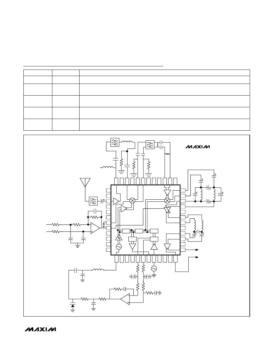
Figure 1. Typical Application Circuit
1
2
3
4
5
6
7
8
9
10
11
12
13
14
15
16
17
18
19
20
21
22
23
24
48
47
46
45
44
43
42
41
40
39
38
37
36
35
34
33
32
31
30
29
28
27
26
25
/2
/6
/8
PFD
/6
20MHz
TO DSP
V
CC
AGC
GAIN SET
MAX4122
MAX4122
MAX2740
PIN
NAME
FUNCTION
43
RFMIX_OUT-
RF Mixer Inverted Input (same as RFMIX_OUT+)
44
RFMIX_OUT+
Open Emitter Output of the RF Downconverter. This pin requires an external pull-down resistor of
1.2k
Ω to establish the correct on-chip bias conditions. Requires a blocking capacitor.
45
VCC_RFMIX
Supply Voltage Pin for RF Downconverter. This pin requires external decoupling of typically
100pF.
46
RFMIX_IN
Input to RF Mixer. Requires a blocking capacitor that may be used as part of the match network.
48
LNA_OUT
LNA Output. Requires a pull-up inductor and a blocking capacitor. These may be configured as
the matching network.