Detailed description, Pin description – Rainbow Electronics MAX1554 User Manual
Page 6
MAX1553/MAX1554
High-Efficiency, 40V Step-Up
Converters for 2 to 10 White LEDs
6
_______________________________________________________________________________________
Detailed Description
Control Scheme
The MAX1553/MAX1554 utilize a minimum off-time, cur-
rent-limited control scheme. If the voltage at FB drops
below the regulation threshold, the internal low-side
MOSFET turns on and the inductor current ramps up to
the current limit. Once the current-limit comparator
trips, the low-side MOSFET turns off for the minimum
off-time (250ns). After 250ns, if the voltage at FB is
above the regulation threshold, the low-side MOSFET
stays off. If the voltage at FB is below the regulation
point, the low-side MOSFET turns back on and the
cycle repeats. By using a regulation control scheme
that is not fixed frequency and that can skip pulses, the
MAX1553/MAX1554 operate with very high efficiency.
Soft-Start
Soft-start is provided on the MAX1553/MAX1554 to min-
imize inrush current. The soft-start time is set with an
external capacitor, C3 (Figures 1, 2, and 3). Use the fol-
lowing equation to solve for C3:
where t
SS
is the soft-start time. A value of 0.1µF pro-
vides a soft-start time of 20ms.
Shutdown
The MAX1553/MAX1554 feature a low-current shut-
down feature. When EN is low, the IC turns off, reduc-
ing its supply current to approximately 0.1µA. For
normal operation, drive EN high or connect to V
CC
.
Overvoltage Protection
The MAX1553/MAX1554 have an adjustable overvoltage-
protection circuit. When the voltage at OV reaches the
overvoltage threshold (1.25V typ), the protection circuitry
prevents the internal MOSFET from switching, allowing
the output voltage to decay.
The peak output voltage in an overvoltage-protection
event is set with a resistor-divider from the output con-
nected to OV (R2 and R3 in Figures 1, 2, and 3). Select
a value for R3 (10k
Ω is recommended), then solve for
R2 using the following equation:
where V
OV
is the overvoltage threshold (1.25V typ), and
V
OUT(PEAK)
is the desired peak output voltage.
R
R
x
V
V
OUT PEAK
OV
2
3
1
=
−
(
)
C
x
tSS
3
2
10
5
=
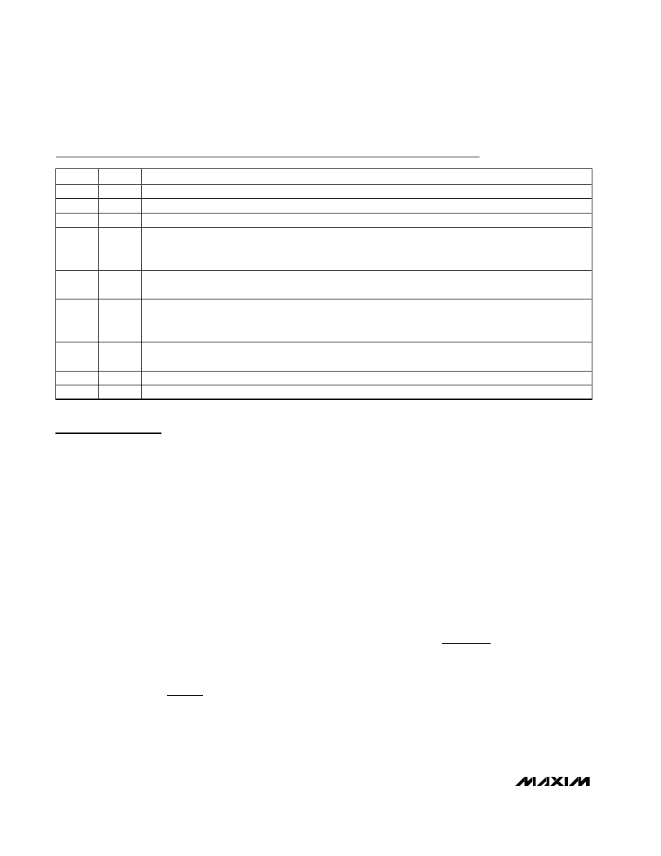
Pin Description
PIN
NAME
FUNCTION
1
GND
Ground
2
V
CC
Voltage-Supply Input. 2.7V to 5.5V. The IC is powered from V
CC
.
3
EN
Enable Input. Drive high or connect to V
CC
to enable the IC. Drive EN low for shutdown.
4
BRT
Brightness-Control Input. Either an analog or PWM control signal can be used. The LED current can be
controlled over a 10 to 1 range. The PWM signal must be between 100Hz and 10kHz, and must have an
amplitude greater than 1.72V.
5
FB
Feedback Input. Connect to the cathode of the LED string and connect a resistor from FB to GND to set the
LED current.
6
SS
Soft-Start Timing-Control Input. Connect a capacitor from SS to GND to control soft-start timing. See the Soft-
Start section for information on selecting the soft-start capacitor. SS is pulled to ground with an internal 200
Ω
switch when EN is low.
7
OV
Overvoltage Sense. Connect to a resistor-divider from the anode of the LED string to set the overvoltage
threshold. See Figures 1, 2, and 3.
8
LX
Inductor Connection. Connect to the inductor and diode. LX is high impedance when EN is low.
—
EP
Exposed Pad. Connect to GND.