Typical operating characteristics (continued), Pin description – Rainbow Electronics MAX1676 User Manual
Page 6
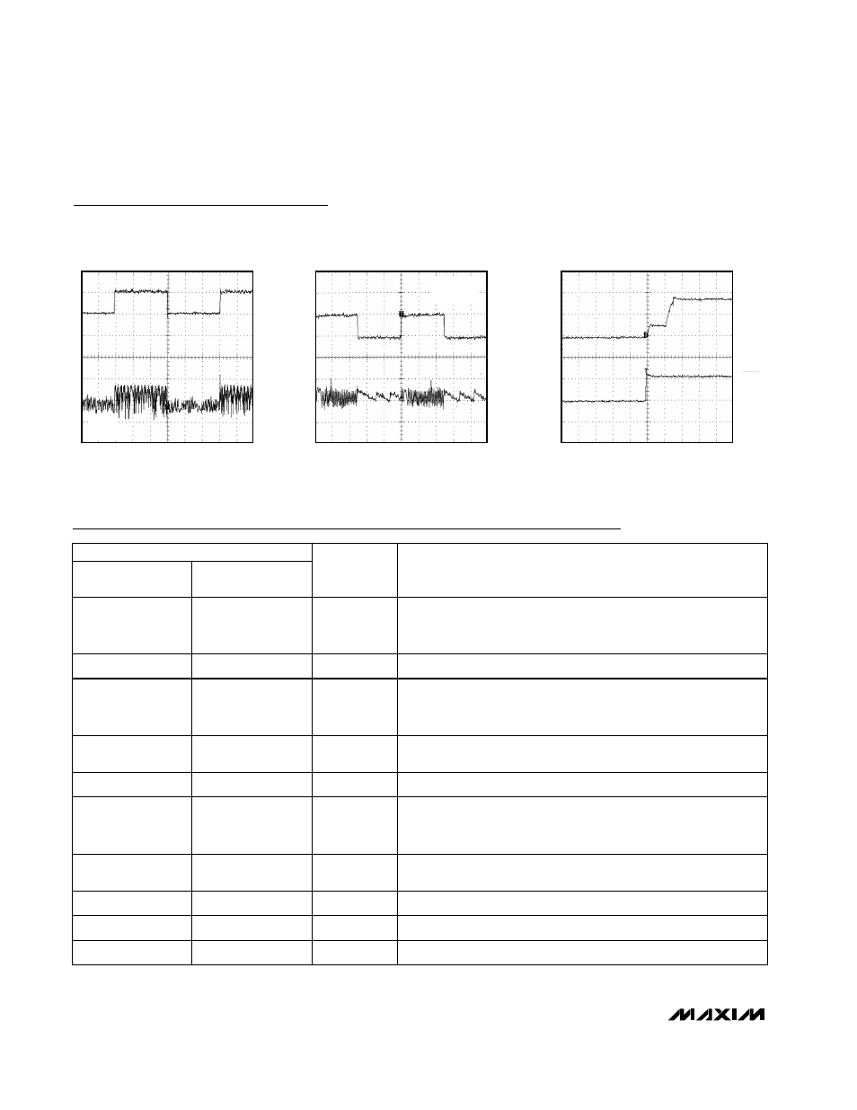
10
µs/div
LINE-TRANSIENT RESPONSE
MAX1674 TOC15
V
IN
2V TO 3V
1V/div
V
OUT
AC COUPLED
100mV/div
I
LOAD
100mA
5
µs/div
LOAD-TRANSIENT RESPONSE
MAX1674 TOC16
I
OUT
200mA/div
V
OUT
50mV/div
AC
COUPLED
V
IN
= 2.4V
V
OUT
= 3.3V
500
µs/div
EXITING SHUTDOWN
MAX1674 TOC17
V
SHDN
2V/div
V
OUT
2V/div
MAX1674/MAX1675/MAX1676
High-Efficiency, Low-Supply-Current,
Compact, Step-Up DC-DC Converters
6
_______________________________________________________________________________________
Typical Operating Characteristics (continued)
(L = 22µH, C
IN
= 47µF, C
OUT
= 47µF
0.1µF, C
REF
= 0.1µF, T
A
= +25°C, unless otherwise noted.)
Pin Description
PIN
NAME
FUNCTION
MAX1674
MAX1675
MAX1676
1
1
FB
Dual-Mode™ Feedback Input. Connect to GND for +5.0V output.
Connect to OUT for +3.3V output. Use a resistor network to set the
output voltage from +2.0V to +5.5V.
2
2
LBI
Low-Battery Comparator Input. Internally set to trip at +1.30V.
3
3
LBO
Open-Drain Low-Battery Comparator Output. Connect LBO to OUT
through a 100k
Ω resistor. Output is low when V
LBI
is <1.3V. LBO is
high impedance during shutdown.
—
4
CLSEL
Current-Limit Select Input. CLSEL = OUT sets the current limit to 1A.
CLSEL = GND sets the current limit to 0.5A.
4
5
REF
1.3V Reference Voltage. Bypass with a 0.1µF capacitor.
5
6
SHDN
Shutdown Input. Drive high (>80% of V
OUT
) for operating mode.
Drive low (<20% of V
OUT
) for shutdown mode. Connect to OUT for
normal operation.
—
7
BATT
Battery Input and Damping Switch Connection. If damping switch is
unused, leave BATT unconnected.
6
8
GND
Ground
7
9
LX
N-Channel and P-Channel Power MOSFET Drain
8
10
OUT
Power Output. OUT provides bootstrap power to the IC.
Dual-Mode is a trademark of Maxim Integrated Products.