Chip information package information – Rainbow Electronics MAX1676 User Manual
Page 12
MAX1674/MAX1675/MAX1676
High-Efficiency, Low-Supply-Current,
Compact, Step-Up DC-DC Converters
12
______________________________________________________________________________________
TRANSISTOR COUNT: 751
Chip Information
Package Information
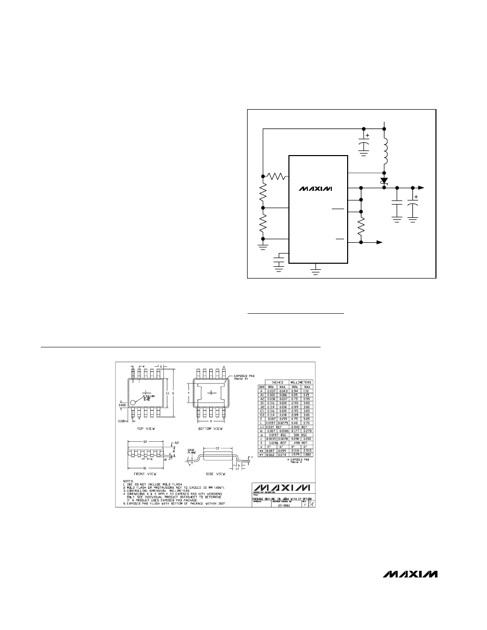
Optional External Rectifier
Although not required, a Schottky diode (such as the
MBR0520) connected between LX and OUT allows
lower start-up voltages (Figure 10) and is recommend-
ed when operating at input voltages below 1.3V. Note
that adding this diode provides no significant efficiency
improvement.
PC Board Layout and Grounding
Careful printed circuit layout is important for minimizing
ground bounce and noise. Keep the IC’s GND pin and
the ground leads of the input and output filter capaci-
tors less than 0.2in (5mm) apart. In addition, keep all
connections to the FB and LX pins as short as possi-
ble. In particular, when using external feedback resis-
tors, locate them as close to the FB as possible. To
maximize output power and efficiency and minimize
output ripple voltage, use a ground plane and solder
the IC’s GND directly to the ground plane.
MAX1674
MAX1675
MAX1676
BATT
(MAX1676)
V
IN
LBI
REF
GND
R3
R1
200
Ω
R4
R2
100k
22
µH
47
µF
0.1
µF
LX
LBO
FB
SHDN
OUT
LOW-BATTERY
OUTPUT
0.1
µF
MBR0520
47
µF
CLSEL
(MAX1676)
Figure 10. Adding a Schottky Diode for Low Input Voltage
Operation
10LUMAX.EPS