Applications information, Inductor selection – Rainbow Electronics MAX1676 User Manual
Page 10
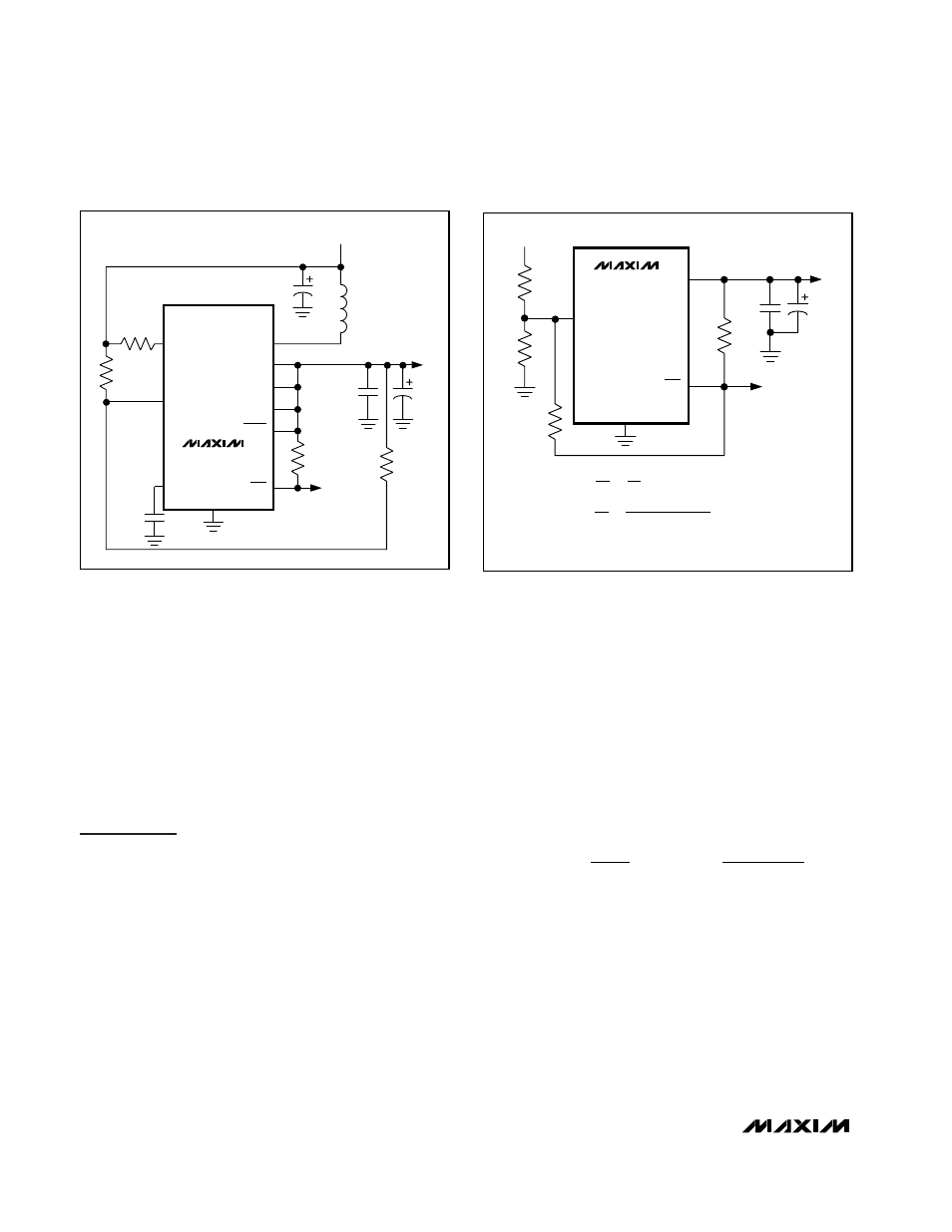
MAX1674/MAX1675/MAX1676
LBI and LBO. For V
TRIP
less than 1.3V, configure the
comparator as shown in Figure 8. Calculate the value of
the external resistors R3 and R4 as follows:
R3 = R4(V
REF
- V
TRIP
) / (V
OUT
- V
REF
)
Since the low-battery comparator is noninverting, exter-
nal hysteresis can be added by connecting a resistor
between LBO and LBI as shown in Figure 9. When LBO
is high, the series combination of R2 and R7 source
current into the LBI summing junction.
Applications Information
Inductor Selection
An inductor value of 22µH performs well in most appli-
cations. The MAX1674/MAX1675/MAX1676 will also
work with inductors in the 10µH to 47µH range. Smaller
inductance values typically offer a smaller physical size
for a given series resistance, allowing the smallest
overall circuit dimensions. However, due to higher peak
inductor currents, the output voltage ripple (I
PEAK
x
output filter capacitor ESR) also tends to be higher.
Circuits using larger inductance values exhibit higher
output current capability and larger physical dimen-
sions for a given series resistance. The inductor’s incre-
mental saturation current rating should be greater than
the peak switch-current limit, which is 1A for the
MAX1674, 500mA for the MAX1675, and 1A or 0.5A for
the MAX1676. However, it is generally acceptable to
bias the inductor into saturation by as much as 20%,
although this will slightly reduce efficiency. Table 1 lists
suggested components.
The inductor’s DC resistance significantly affects effi-
ciency. See Table 2 for a comparison of inductor speci-
fications. Calculate the maximum output current as
follows:
where I
OUT(MAX)
= maximum output current in amps
V
IN
= input voltage
L = inductor value in µH
η = efficiency (typically 0.9)
t
OFF
= LX switch’s off-time in µs
I
LIM
= 0.5A or 1.0A
I
V
V
I
t
V
V
x L
OUT MAX
IN
OUT
LIM
OFF
OUT
IN
( )
=
–
–
2
η
High-Efficiency, Low-Supply-Current,
Compact, Step-Up DC-DC Converters
10
______________________________________________________________________________________
MAX1674
MAX1675
MAX1676
BATT
(MAX1676)
V
IN
LBI
REF
GND
R3
R1
200
Ω
R4
22
µH
47
µF
0.1
µF
LX
LBO
V
OUT
FB
R2
100k
SHDN
OUT
CLSEL
(MAX1676)
LOW-
BATTERY
OUTPUT
0.1
µF
47
µF
Figure 8. Setting Resistor Values for the Low-Battery Indicator
when V
IN
< 1.3V
MAX1674
MAX1675
MAX1676
LBI
GND
V
TRIP
(V
H
, V
L
)
R3
R4
R7
V
H
IS THE UPPER TRIP LEVEL
V
L
IS THE LOWER TRIP LEVEL
WHERE
R2
100k
LBO
OUT
V
OUT
0.1
µF
47
µF
V = 1.3V
V = 1.3V
H
L
( )
+
+
( )
+
−
−
+
(
.
)
( .
) (
)
1
3
7
3
4
1
3
4
1 3
3
1 3
2
7
R
R
R
R
R
R
V
V R
V
R
R
OUT
Figure 9. Adding External Hysteresis to the Low-Battery
Indicator