Max2114 dbs direct downconverter, Pin description (continued) – Rainbow Electronics MAX2114 User Manual
Page 7
MAX2114
DBS Direct Downconverter
_______________________________________________________________________________________
7
Pin Description (continued)
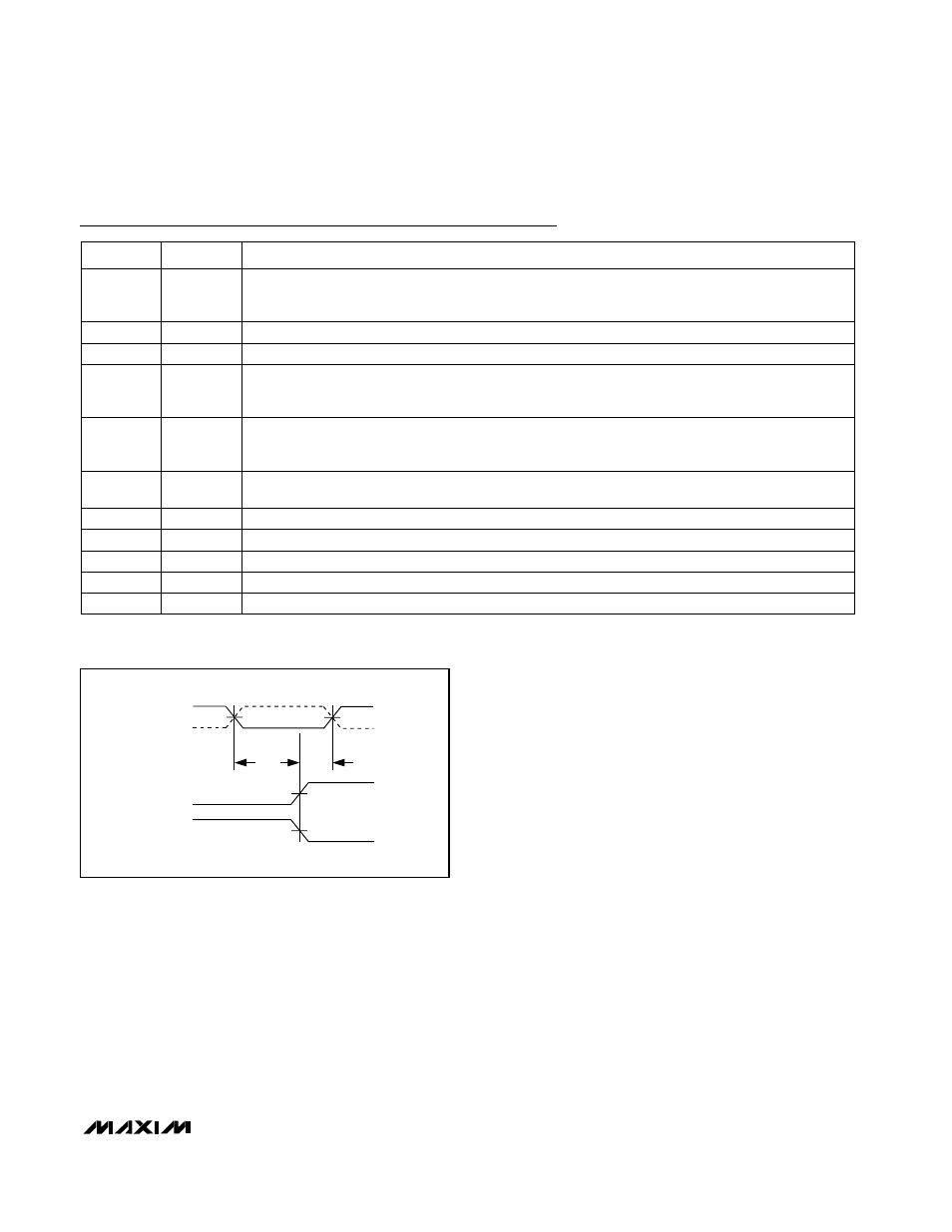
50%
MOD+,
MOD-
PSOUT+
PSOUT-
50%
50%
50%
t
SUM
t
HM
Figure 1. Modulus Control Timing Diagram
Voltage Drive Output. Control of external charge-pump transistor.
CP
44
Feedback Input for Loop Filter
FB
43
LO Tank Oscillator Input. Connect to an external LC tank with varactor tuning.
TANK+
40
LO Internal Regulator. Bypass with a 1000pF ceramic chip capacitor to GND.
VRLO
39
LOBUFSEL = GND: PECL Prescaler Output. Differential output of the dual-modulus prescaler. Used in
conjunction with PSOUT+. Requires PECL-compatible termination. LOBUFSEL = V
CC
: 50
Ω LO buffer
inverting output.
LOBUF-/
PSOUT-
35
LO Tank Oscillator Input. Connect to an external LC tank with varactor tuning.
TANK-
38
PECL Phase-Locked Loop Input. Drive with a differential PECL signal in conjunction with PLLIN+ (pin 32).
PLLIN-
33
LOBUFSEL = GND: PECL Prescaler Output. Differential output of the dual-modulus prescaler. Used in
conjunction with PSOUT-. Requires PECL-compatible termination. LOBUFSEL = V
CC
: 50
Ω LO buffer
noninverting output.
LOBUF+/
PSOUT+
34
PECL Phase-Locked Loop Input. Drive with a differential PECL signal in conjunction with PLLIN- (pin 33).
PLLIN+
32
PECL Modulus Control. A PECL low on MOD- sets the dual-modulus prescaler to divide by 32. A
PECL logic high sets the divide ratio to 33. Drive with a differential PECL signal in conjunction with
MOD+ (pin 30).
MOD-
31
PIN
FUNCTION
NAME
LO Buffer Divider Ratio Input. Drive high to enable divide-by-one LO buffer output. Connect to GND to
enable divide-by-two buffer output.
LODIVSEL
37