Rainbow Electronics MAX1709 User Manual
Page 9
MAX1709
4A, Low-Noise, High-Frequency,
Step-Up DC-DC Converter
_______________________________________________________________________________________
9
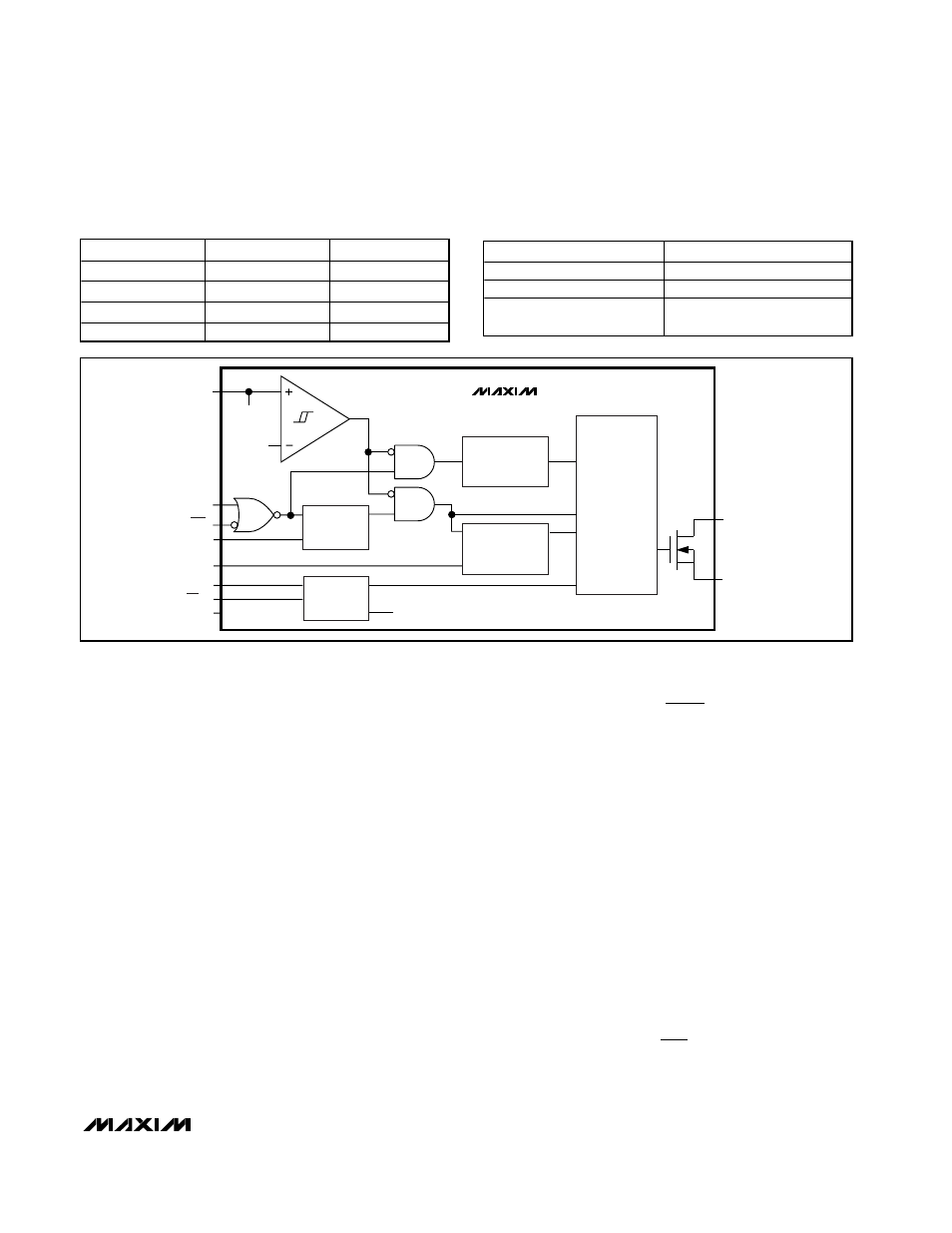
troller functional diagram. The MAX1709 enters syn-
chronized current-mode PWM when a clock signal
(350kHz < f
CLK
< 1000kHz) is applied to CLK. For
wireless or noise-sensitive applications, this ensures
that switching harmonics are predictable and kept out-
side the IF frequency band(s). High-frequency opera-
tion permits low-magnitude output ripple voltage and
minimum inductor and filter capacitor size. Switching
losses will increase at the higher frequencies (see
Power Dissipation).
Setting the Output Voltage
The MAX1709 features Dual Mode™ operation. When
FB is connected to ground, the MAX1709 generates a
fixed output voltage of either +3.3V or +5V, depending
on the logic applied to the 3.3/5 input (Figure 1). The
output can be configured for other voltages, using two
external resistors as shown in Figure 4. To set the out-
put voltage externally, choose an R3 value that is large
enough to minimize load at the output but small enough
to minimize errors due to leakage and the time constant
to FB. A value of R4
≤
50k
Ω is required.
where V
FB
= 1.24V.
Soft-Start/Current-Limit Adjustment
(SS/LIM)
The soft-start pin allows the soft-start time to be adjust-
ed by connecting a capacitor from SS/LIM to ground.
Select capacitor C3 (connected to SS/LIM pin) as:
C3 (in µF) = 3.2
✕
t
SS
where t
SS
is the time (in seconds) it takes the switch
current limit to reach full value.
To improve efficiency or reduce inductor size at
reduced load currents, the current limit can be reduced
from its nominal value (see Electrical Characteristics).
A resistor (R1 in Figure 1) between SS/LIM and ground
reduces the current limit as follows:
R
k
I
I
R
k
LIM
1
312 5
1
312 5
1
.
.
=
×
≤
(
)
Ω
Ω
R
R
V
V
OUT
FB
3
4
1
=
−
_______________________________________________________________________________________
ONA
ONB
MAX1709
0
0
On
0
1
Off
1
0
On
1
1
On
Figure 2. Simplified Functional Diagram
Table 2. Selecting Switching Frequency
Table 1. On/Off Logic Control
CLK
MODE
0
Not allowed
1
PWM
External clock
(350kHz
−1000kHz)
Synchronized PWM
N
PWM
CONTROLLER
STARTUP
OSCILLATOR
SEE
FIGURE 3.
OSC
UNDERVOLTAGE LOCKOUT
FB
EN
D
EN
Q
600kHz
OSCILLATOR
EN
REFERENCE
ON
RDY
DUAL MODE
FB
LX
PGND
1.260V
2.15V
OUT
ONA
ONB
REF
CLK
FB
3.3/5
GND
IC POWER
MAX1709
OUT
Dual Mode is a trademark of Maxim Integrated Products.