Detailed description – Rainbow Electronics MAX1709 User Manual
Page 8
MAX1709
4A, Low-Noise, High-Frequency,
Step-Up DC-DC Converter
8
_______________________________________________________________________________________
_______________Detailed Description
The MAX1709 step-up converter offers high efficiency
and high integration for high-power applications. It
operates with an input voltage as low as 0.7V and is
suitable for single- to 3 cell battery inputs as well as
2.5V or 3.3V regulated supply inputs. The output volt-
age is preset to +3.3V or +5.0V or can be adjusted with
external resistors for voltages between +2.5V to +5.5V.
The MAX1709 internal N-channel MOSFET switch is
rated for 10A (RMS value) and can deliver loads to 4A,
depending on input and output voltages. For flexibility,
the current limit and soft-start rate are independently
programmable.
A 600kHz switching frequency allows for a small induc-
tor to be used. The switching frequency is also syn-
chronizable to an external clock ranging from 350kHz
to 1000kHz.
ONA,
ONB
The logic levels at ONA and ONB turn the MAX1709 on
or off. When ONA = 1 or ONB = 0, the part is on. When
ONA = 0 and ONB = 1, the part is off (Table 1). Logic
high on control can be implemented by tying ONB high
and using ONA for shutdown. Implement inverted sin-
gle-line on/off control by grounding ONA and toggling
ONB. Implement momentary pushbutton On/Off as
described in the Applications Information section. Both
inputs have approximately 0.15V of hysteresis.
Switching Frequency
The MAX1709 switches at the fixed-frequency internal
oscillator rate (600kHz) or can be synchronized to an
external clock. Connect CLK to OUT for internal clock
operation. Apply a clock signal to CLK to synchronize
to an external clock. The frequency can be changed on
the fly. The MAX1709 will synchronize to a new external
clock rate in two cycles and will take approximately
40µs to revert to its internal clock frequency once the
external clock pulses stop and CLK is driven high.
Table 2 summarizes oscillator operation.
Operation
The MAX1709 switches at a constant frequency
(600kHz) and modulates the MOSFET switch pulse
width to control the power transferred per cycle and
regulate the voltage across the load. In low-noise appli-
cations, the fundamental and the harmonics generated
by the fixed switching frequency are easily filtered out.
Figure 2 shows the simplified functional diagram for the
MAX1709. Figure 3 shows the simplified PWM con-
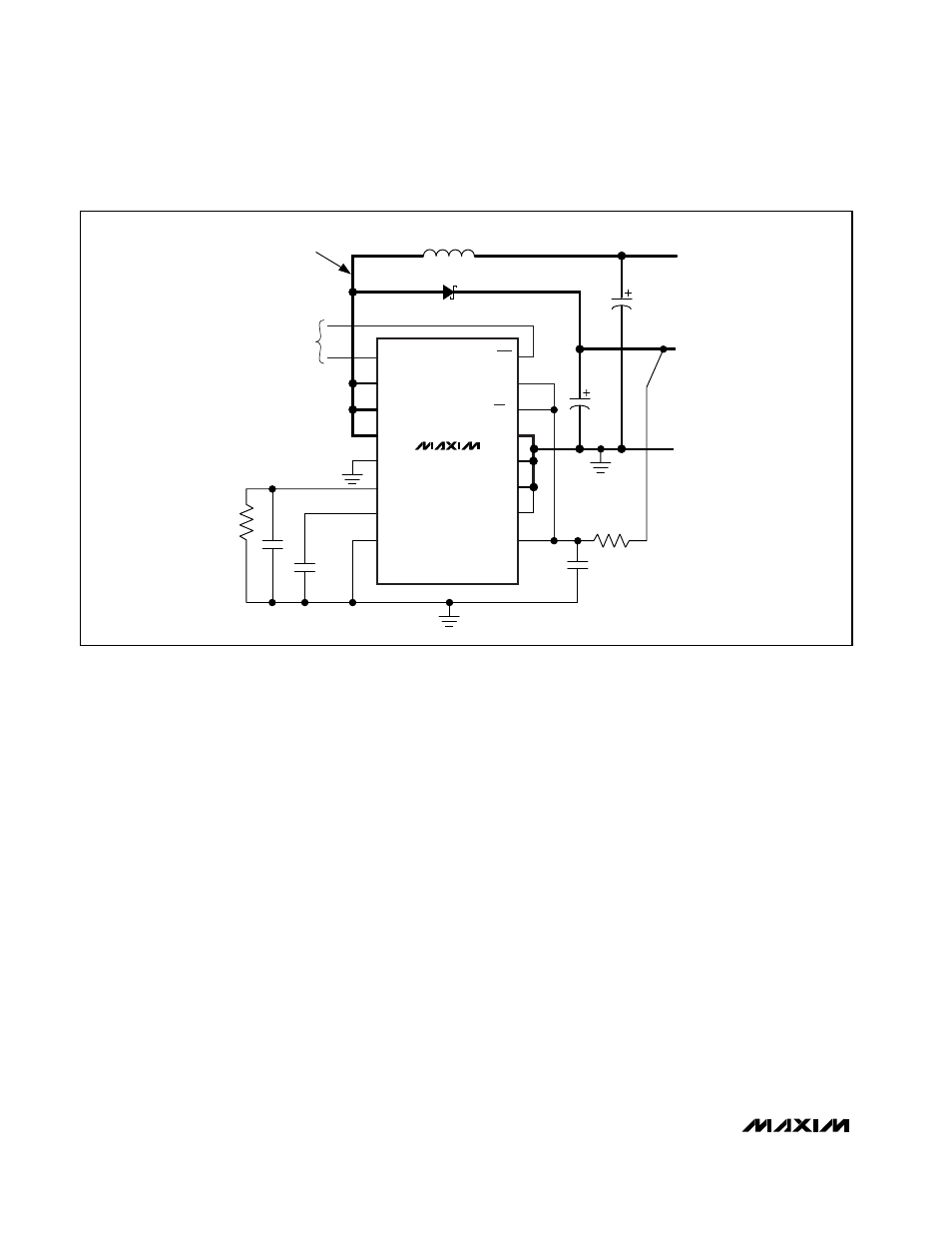
Figure 1. Standard Operating Circuit
R2
2
Ω
GND
D1
L1
ONA
LX
LX
LX
GND
SS/LIM
REF
GND
ONB
CLK
3.3/5
PGND
PGND
PGND
FB
OUT
KEEP TRACES
SHORT AND WIDE
R1
C3
C4
0.22
µF
C5
0.1
µF
C6, C7
2 x
150
µF
1
µH
V
OUT
5V
V
IN
1V TO 5V
ON-OFF
CONTROL
MAX1709
C1, C2
2 x 150
µF