Electrical characteristics (continued) – Rainbow Electronics MAX1709 User Manual
Page 4
Note 1: Output voltage is specified at 1A switch current I
SW
, which is equivalent to approximately 1A
✕
(V
IN
/ V
OUT
) of load current.
Note 2: Load regulation is measured by forcing specified switch current and straight-line calculation of change in output voltage in
external feedback mode. Note that the equivalent load current is approximately I
SW ✕
(V
IN
/ V
OUT
).
Note 3: Until undervoltage lockout is reached, the device remains in startup mode. Do not apply full load until this voltage is
reached.
Note 4: Startup is tested with Figure 1’s circuit. Output current is measured when both the input and output voltages are applied.
Note 5: Minimum operating voltage. The MAX1709 is bootstrapped and will operate down to a 0.7V input once started.
Note 6: Supply current is measured from the OUT pin to the output voltage (+3.3V). This correlates directly with actual input supply
current but is reduced in value according to the step-up ratio and efficiency.
Note 7: ONA and ONB inputs have approximately 0.15V hysteresis.
Note 8: Guaranteed by design, not production tested.
Note 9: Specifications to -40°C are guaranteed by design, not production tested.
MAX1709
4A, Low-Noise, High-Frequency,
Step-Up DC-DC Converter
4
_______________________________________________________________________________________
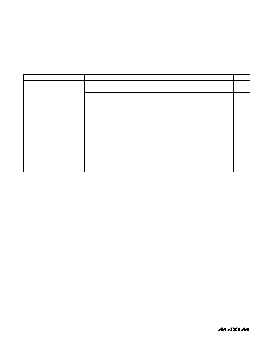
ELECTRICAL CHARACTERISTICS (continued)
(V
OUT
= V
CLK
= +3.6V, ONA = ONB = FB = GND, T
A
= -40°C to +85°C, unless otherwise noted.) (Note 9)
PARAMETER
CONDITIONS
MIN
TYP
MAX
UNITS
ONA, ONB, 3.3/5, 1.2V < V
OUT
< 5.5V
0.2
×
V
OUT
V
Input Low Level (Note 7)
CLK, 2.7V < V
OUT
< 5.5V
0.2
×
V
OUT
ONA, ONB, 3.3/5, 1.2V < V
OUT
< 5.5V
0.8
×
V
OUT
Input High Level
CLK, V
OUT
= 5.5V
0.8
×
V
OUT
V
Logic Input Current
ONA, ONB, CLK, 3.3/5
1
µA
Internal Oscillator Frequency
500
700
kHz
Maximum Duty Cycle
80
95
%
External Clock Frequency
Range
350
1000
kHz
CLK/SEL Pulse Width
(Note 8)
100
ns
CLK/SEL Rise/Fall Time
(Note 8)
50
ns